Does anyone know how to model a shunt regulator in PSUD? I know it must be more than a current tap because the regulator drops some voltage and a series resistor and current tap would be an illegal combination, or rather unchoseable.
I am trying to model an LC > Janus shunt regulator > maybe another LC for channel seperation.
I am trying to model an LC > Janus shunt regulator > maybe another LC for channel seperation.
JoshK said:I am trying to model an LC > Janus shunt regulator > maybe another LC for channel seperation.
I can't answer the original question, but I had a regulator followed by an RC for channel separation -- ruined the amp. Jumpering over the R was transformative.
JoshK said:As best as I can tell you don't model a regulator in PSUD.
Dave, thanks for your experience.
It's Doug: http://www.diyaudio.com/forums/showthread.php?postid=1288215#post1288215
EC8010 said:Any regulator looks like a constant current load looking into its input.
Not particularly sure what all that implies to my question. Do you mean that anything thereafter is moot as it shield the prior passives from the suceeding stages?
I think he was referring to the load that the filter sees. For a shunt regulator, this is obvious. For a series regulator, the load is the collector of the pass transistor, which has a high dynamic impedance.
dsavitsk: Your experience with the RC after the reg is an illustrative example of what happens when you kill the dynamic regulation.
dsavitsk: Your experience with the RC after the reg is an illustrative example of what happens when you kill the dynamic regulation.
SY said:dsavitsk: Your experience with the RC after the reg is an illustrative example of what happens when you kill the dynamic regulation.
And how! It was a good lesson learned -- the resistance was small (20R) and the caps after are relatively large, but I could never quite get the amp right.
This brings up a question: when modeling a PS in PSUD, I generally check for ringing by using the stepped load function. PSUD will show the change in voltage at the load, but the speed at which it changes can differ (in the supplies I've been playing with, it is usually between .5 and 1 second with a 2mA change in draw). So, do I want that change to be fast or slow?
IMO, the speed is less important than the absence of ringing. So many of these multi-LC jobs, designed rather than engineered, ring like chimes... Anyway, ideally it would be as slow as possible- perfect regulation would be a voltage that never shifted. But most important, no ringing.
So many of these multi-LC jobs, designed rather than engineered, ring like chimes...
Can you explain the nature of this ringing? I only ever see it on PSUD sims.
John
I haven't tried the stepped load until now. If I estimate my Aikido linestage draws 34mA of current and the regulator ~50mA (I know I probably don't need a regulator but this is a learning project) then what would be a good second value for the stepped load? Basically how much of a change?
I used 100mA after 84mA after 1sec. Is this ripple considered ringing?
I used 100mA after 84mA after 1sec. Is this ripple considered ringing?
Attachments
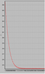
John, I found the sims pretty accurate. If you hit one of those LCLCLC monstrosities with a current step (for example, when clipping or even going out of class A), the ringing on recovery is pretty easy to see. To do it on the bench is pretty easy- calculate what R you need for the lower current and hang it off the supply. Then calculate what resistance you need in parallel to draw the higher current, put it in the collector of an HV power transistor, then drive the base with a square wave.
The reason for the ringing is usually pretty obvious, and if one engineers it properly (spreading the poles and keeping the Q of each section relatively low), it can be made to work very well. But that's unfortunately all too often not the case.
The reason for the ringing is usually pretty obvious, and if one engineers it properly (spreading the poles and keeping the Q of each section relatively low), it can be made to work very well. But that's unfortunately all too often not the case.
The reason for the ringing is usually pretty obvious, and if one engineers it properly (spreading the poles and keeping the Q of each section relatively low), it can be made to work very well. But that's unfortunately all too often not the case.
I see. The reason I asked is that I use an LCLCLC power supply on my phono stage and no ringing shows up at turn-on. Obviously a phono pre-amp won't induce any radical current demands on its power supply during use and ripple is non-existant with an LCLCLC, even with only 51uF on each section. Of course regulation is tight as well.
You had me worried enough that I did a simulation and found a very low frequency but quickly damped oscillation at turn-on that doesn't really qualify as ringing. What is the frequency and maximum p-p ripple voltage of the ringing you measured on the bench?
John
Awww, you want me to dig up old lab notebooks!  Order of magnitude, a few volts above and below the exponential drop on a low frequency square wave (equivalent to a step) for 20-30mA sorts of current levels and 200-300V, using three LC sections. Tuning the square wave frequency can really get things moving. Some of the sims I've done for supplies under discussion on the forum show worse behavior than that, dozens of volts, but I haven't had the really pathological examples on the test bench.
I'll bet a little redistributing of your capacitance could smooth out any overshoot while retaining the low noise. If you can do that, I'd be very interested in your subjective impression of the sonic effects.
Order of magnitude, a few volts above and below the exponential drop on a low frequency square wave (equivalent to a step) for 20-30mA sorts of current levels and 200-300V, using three LC sections. Tuning the square wave frequency can really get things moving. Some of the sims I've done for supplies under discussion on the forum show worse behavior than that, dozens of volts, but I haven't had the really pathological examples on the test bench.I'll bet a little redistributing of your capacitance could smooth out any overshoot while retaining the low noise. If you can do that, I'd be very interested in your subjective impression of the sonic effects.
JoshK said:I haven't tried the stepped load until now. If I estimate my Aikido linestage draws 34mA of current and the regulator ~50mA (I know I probably don't need a regulator but this is a learning project) then what would be a good second value for the stepped load? Basically how much of a change?
I used 100mA after 84mA after 1sec. Is this ripple considered ringing?
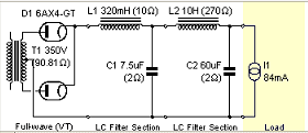
What you see there is not ringing, just ripple. That really isn't an LCLC supply, at least not at line frequency. The first L is too low in inductance. It's going to behave much more like a cap input CLC supply.
Sheldon
Hi Sheldon,
Thanks for the response. I realize that this isn't technically an LCLC, at first I was trying to do the low dcr thing but I couldn't get it to model well at all. Then I thought I'd leave the first low everything choke in with the hopes that it might have some benefits with HF hash.
Josh
Thanks for the response. I realize that this isn't technically an LCLC, at first I was trying to do the low dcr thing but I couldn't get it to model well at all. Then I thought I'd leave the first low everything choke in with the hopes that it might have some benefits with HF hash.
Josh
- Status
- This old topic is closed. If you want to reopen this topic, contact a moderator using the "Report Post" button.
- Home
- Amplifiers
- Tubes / Valves
- PSUD2 Q on regulator