Hi Folks,
For anyone who has been following my project and for all those who have helped out, this is where I am up to.
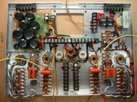
I have now finished most of the circuitry and I am in the process of wiring it all together. The only 'kit' part is the SDS lads power supply kit which seemed to good to go past. The rest is point to point wired with my own layout. The plate that you can see in the picture will then be mounted into the chassis which is currently away at the electroplaters.
I think that I will be ready to power it up for a test run in a week or so and will let you know how it goes. I am sure that I will need substantial help at this time!!
Rob
For anyone who has been following my project and for all those who have helped out, this is where I am up to.
I have now finished most of the circuitry and I am in the process of wiring it all together. The only 'kit' part is the SDS lads power supply kit which seemed to good to go past. The rest is point to point wired with my own layout. The plate that you can see in the picture will then be mounted into the chassis which is currently away at the electroplaters.
I think that I will be ready to power it up for a test run in a week or so and will let you know how it goes. I am sure that I will need substantial help at this time!!
Rob
Attachments
First time!
Sweet wire job!
It seems you've planned it out very well, personally I would have opted for a deeper chassis....& I would have wound the heater wires tighter (More turns per inch ).
But your layout is superb.....a breath of fresh air considering the wretched tangles of commercial designs!
Lets' see the signal wiring please.... so we can compare this stage side by side with the completed version.
Time for some new iron tips?
_________________________________Rick.........
Attachments

Thanks for the comments. It is a version of the Dynaco 70. Yes, I probably have been a bit liberal with the solder - unfortunately I can't blame the iron as it is new. As for the heater wires, I tried to get them tighter but it is 18g cloth wire and very stiff. Maybe I should have tried harder but it is too late to undo it all now. I will now just cross my fingers tightly and hope that it is tight enough... I will post some follow up pictures later.
Thanks again for the comments.
Rob
Thanks again for the comments.
Rob
Richard,
Sorry, missed your comment about the Chassis. What you can see in the picture is merely a middle plate. The actual chassis is much deeper, approximately 65mm. The plate that you can see sits just 5mm under the top plate which is unmarked apart from the holes for the valves. This 'top plate' and the actual chassis is currently being electroplated. I designed it this way so that I could work on all the functional bits without damaging the display part. Also has the advantage of enabling me to work on the amp whilst the chassis is being finished.
Cheers,
Rob
- Status
- This old topic is closed. If you want to reopen this topic, contact a moderator using the "Report Post" button.
- Home
- Amplifiers
- Tubes / Valves
- 1st Project - Half time report