seems like it would add even harmonic distortion (or maybe that's what the advertisers mean by "detail")..... that's the whole reason for using matched tubes and balanced output xfmrs, to minimize distortion...... unbalanced xfmrs might sound good in a guitar amp, but for hi-fi, it's a source of distortion.
I read about this trick several years ago, and even did several experiments. The theory goes like this:
Every transformer (or electromagnetic device) has two non linear regions. One is near zero current, and the other is the saturation region. Look up "BH curves". We all know about saturation in a transformer, and the resulting ugly sounding distortion. There is another, much smaller non linear region where some of the initial energy applied to the tansformer is used up magnetizing the core without generating any current in the secondary. This leads to a "dead zone" around the zero net current region.
This effect does not come into play in a SE amp since the DC current flowing through the transformer primary biases the transformer right into the center of its linear region. The transformer in a P-P amp ideally has no net magnetizing force at idle, so the non linear region occupies the center of the important "first watt" zone. When a P-P amp is used with efficient speakers the effect can be a loss of detail and a "dull sound".
It is possible to move the "dead zone" away from the "first watt" region by applying a significant offset in bias current of the output tubes. The tubes must be biased hot enough so that the tube with the lowest current does not generate distortion. This technique works best with class A P-P amp designs. A significant DC offset requires a gap in the transformer core, which then reduces the primary inductance, requiring a much larger transformer.
My experiments used an 80 watt guitar amp transformer ( I have a lot of them) similar to the one I used in the 300Beast (30 watt P-P). I restacked the core to include a gap, which was optimized to allow the transformer to work in a SE amp.
I tested the modified transformer with the idea of building an asymetrical P-P amp for HiFi purposes, and believe that the idea has some merit for lower powered P-P amps (I was making 10 watts). I came to the conclusion that it would just be easier to build an SE amp.
These experiments quickly lead to the idea that the asymetrical P-P amp had some serious use as a guitar amp. It is possible to use two different output tubes, at two different bias currents, to build an amp that sounds clean up to a point, then transitions to nasty abruptly without needing to be extremely loud. Much more experimenting is needed here.
Or, you can use a PP OPT that does not suffer from hysteresis induced zero crossing problems. They do exsist.
Either amorphous core or clever E/I core construction, take your pick and pay the price.
Even guitar OPT's are available, that perform in this fashion, ask Andy Marshall at THD, or check out the new Gibson Amplifiers. Or, for that matter, the new Sylken amps.
Bud
Either amorphous core or clever E/I core construction, take your pick and pay the price.
Even guitar OPT's are available, that perform in this fashion, ask Andy Marshall at THD, or check out the new Gibson Amplifiers. Or, for that matter, the new Sylken amps.
Bud
Don't put unbalanced DC into a toroidal OPT unless you know for certain that it has a gap cut into the core ring.
In E/I and C core OPT's you can add DC bias for reduced distortion. Chicago Transformer, Peerless and others did this by deliberately unbalancing the DC resistance in the primary halves. It also messes with the tubes and is not good when the system is called upon for maximum performance.
Better to put a gap in the core and flatten the permeability hump that way instead. That is what DC off set and gaps do and it has a direct relationship to how much distortion you have under 400 Hz. Commercial core does not provide anything but a ferrous focusing window for the B Field event, above 400 Hz, and the increased permeability in the core, as frequency drops, just interferes with the antenna event and creates distortion.
Only problem with either scheme is that you will eat inductance, which is what gives you the reactive load match that provides low frequencies in the first place. Only free lunch is no saturation induced reminance in the core so no zero crossing distortion in PP and no permitivity defined "settling" time on the back half of a signal in a SE OPT either. No way out of inductance equals distortion either.
Bud
Toroidal transformers generally have an intrinsic distributed gap which allows some leeway for DC current mismatch. Inductances in push-pull type OPT's are generally high enough that some may be sacrificed by adding a slight gap which makes the transformer more useful.
John
John
Bud wrote:
"Or, you can use a PP OPT that does not suffer from hysteresis induced zero crossing problems. They do exsist."
Years ago I got hold of a bad output transformer from a Klimo PP amplifier. (made in Germany) It looked like a standard square E-I lamination type. I was going to dismantle and reverse engineer it. I then discovered it wasn't E-I, but what must be described as a figure 8 lamination. That's many thin square figure 8 laminations without any gaps one on top of the other.
In the center was a standard looking winding build that must have been wound bobbin style like a toroid. I neved did get it apart due to it's construction, and never saw another like it in use. I wonder if this was a design for the hysteresis problem in question?
Victor
H0ollow State,
Sounds beguiling. Can you provide a rough sketch so that I am certain I understand what you are saying?
If negotiations with Planet 10 jell, and I am pretty sure they will, they will be a source for zero crossing distortion OPT's. Well, not absolute zero for that stuff, but so close it is very difficult to find, even when driven into saturation. On regular old reliable E/I core too. And, it does eliminate that "dull" hooded sound that PP are famous for.
I can provide an mp3 clip for a guitar amplifier, a stock Vox AC 30 circuit, with one of these transformers as the OPT, if anyone is interested in hearing that sort of thing. Or, you can go play a THD, if you play guitar.
Bud
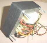
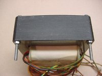
I knew I still had it somewhere. Attached is a photo of the transformer I spoke of. It's from a Klimo "Kent" 35W monoblock using 2 EL34s and 2 ECC83s. Nothing too special except that the transformer had a center tapped tertiary winding that the ECC83 driver cathodes went through.
Look closely at the sides of the iron and you will not see any telltale lines that would indicate E-I laminations. Each lamination is one piece. Winding such a transformer must be very expensive and very time consuming. Each winding must be made by passing a premeasured length of wire through the windows. And probably by hand. I can think of no other way of doing it.
Look closely at the sides of the iron and you will not see any telltale lines that would indicate E-I laminations. Each lamination is one piece. Winding such a transformer must be very expensive and very time consuming. Each winding must be made by passing a premeasured length of wire through the windows. And probably by hand. I can think of no other way of doing it.
Attachments
HollowState,
If this was from a commercial amplifier, then it is from an incredibly expensive one, if the transformer is all hook wound, as large toroids are.
There is a slight possibility that it is an O/I core but I do not see any mechanism for centering the I and holding it, other than varnish. Certainly looks like a square core bobbin.
Somewhat similar idea is used in cruciform lams for constant voltage, called core and frame, but there is a triangular divot in the O, at either end of where the cruciform with it's triangular points fits into the O, and a hole is created there to put a bolt through. You may already know all of this, but others might not.
Were they using the cathodes of the driver tubes to drag the B to zero before H got there? I have trouble envisioning any other use for what would amount to a snubber winding. Certainly not the tortured PP pseudo SE device that McIntosh has used for such a long time, using the cathodes from opposite polarity to collapse the B field and running the plates in physical parallel as they do.
I will have to see if Per L has any idea what this is, quite intriguing.
Thanks for sharing.
Bud
Bud, as far as I know the tertiary winding was a feedback path for the driver stage. I've seen this before in a Rauland amplifier I once repaired. Instead of using resistors from the output plates back to the driver cathodes, they used a winding in the output trans. Designer's choice I guess.
edit: Yes, this was a commercial amplifier made in Germany in the late 80's. Google "Klimo Kent Amplifier" and you'll find a little on it. I saw a price of $4000, but don't remember if it was for one or a pair.
Victor
edit: Yes, this was a commercial amplifier made in Germany in the late 80's. Google "Klimo Kent Amplifier" and you'll find a little on it. I saw a price of $4000, but don't remember if it was for one or a pair.
Victor
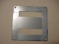
I believe this is a 'finger' type, or 'number 8' lamination. It does indeed have a gap in each laination, on one side of the center finger. The outermost lams are usually different, with only small (few mm) stubs of the center finger left on each side. The transformer is (dis)assembled by lifting one side of the lamination close to the center finger (where the gap is) and pulling it out and over the bobbin. If it was impregnated, it will be practically impossible to dissasemble 
Hey ilimzn,
You're a genius and described it perfectly. The first lamination came out pretty easily doing just as you said. It doesn't seem to be impregnated and using a knife edge to seperate them should do the trick. Thanks for the tip.
I've dismantled many transformers in the past, but never one built like this. They were all American made. This design seems like a better way because the overall gap is less then a similar size EI type would have. I'm surprised that we haven't adopted this method of building the core. Probably because it would cost an extra dime.
And all the lams are the same with no special finishing or keeper types. The fact that the center edge gap was concealed under a shallow lip on the plastic core bobbin through me a curve that I failed to notice.
Victor
edit: spelling
Attachments
- Status
- This old topic is closed. If you want to reopen this topic, contact a moderator using the "Report Post" button.
- Home
- Amplifiers
- Tubes / Valves
- Unbalacing a PP output transformer?