Morning All,
I have finished the wiring for the 'scratch' phono preamp designed by Triode Dick. I think I've got everything squared away and am unclear on only one last thing.
I'm trying to understand the heater wiring for the ECC83 & 5751 valves. The LT supply is outputing a regulated 12.0 VDC. I am currently applying the 12 VDC across pins 4 and 5 of each valve by running hookup wires from the positive terminal of the 10 uF caps to pin 4 of each valve and from the ground leg of the 10uF caps to pin 5 of each valve. As I understand it this is connecting the heaters of each valve in series....am I correct?
The only other thing i can think of is:
o--------4----------4--------------4
12 VDC
0--------5----------5--------------5
Any clarification would be much appreciated.
SY said:What you've described is running them in parallel, not series. And parallel is what you want.
Thanks SY. By 'what you've described' are you referring to the wiring I already have in place (each valve with its own connection to the 12 V) or what I have drawn above (+ cap -> 4 -> 4 -> 4; - cap -> 5 -> 5 -> 5)?
Oh, I see, you mean daisy-chaining instead of individual? Electrically, they're about the same. I tend to daisy chain as much as is practical so that there are fewer AC-carrying wires strewn around the chassis. But it depends on layout- in my EL84 amp, I have a separate twisted pair going to each channel, but the tubes within the channel are daisy-chained.
That's what I meant Sy...wasn't sure if there was going to be a problem by not 'daisy chaining' the valves together.
Here's another question:
I'm using a Hammond 250-0-250 CT transformer for the HT...I'm seeing B+ of 356 VDC as opposed to the 275 as described in the schematic.
250 VRMS x 1.414 = 353.5 VDC
This 353.5 VDC will be less after the rectifier drop...no? So the B+ at the first cap after the rectifier should see something less than 353.5, not more...no?
Shouldn't the EZ80 be dropping a fair amount of voltage across itself?
I don't have the numbers in front of me but the plate voltages were all within spec.
It's the cathode to plate voltage that one has to watch for...right?
TIA
Thanks again Sy.
Bare with me while I try to figure this out...my background is in mechanical engineering and I'm still struggling to fully understand this stuff from the few classes I took.
I need to reduce the total B+ voltage by 81 volts. Can it really be as simple as dropping 27 volts across each of the three resistors that will go in front of each choke?
I think the B+ current is ~ 25 mA so that would require a 1K 1W resistor in front of each choke....please tell me it's that simple.
Oh, I don't need to worry about the heater voltage as it is being supplied by a separate circuit.
cgrums said:That's what I meant Sy...wasn't sure if there was going to be a problem by not 'daisy chaining' the valves together.
Here's another question:
I'm using a Hammond 250-0-250 CT transformer for the HT...I'm seeing B+ of 356 VDC as opposed to the 275 as described in the schematic.
250 VRMS x 1.414 = 353.5 VDC
This 353.5 VDC will be less after the rectifier drop...no? So the B+ at the first cap after the rectifier should see something less than 353.5, not more...no?
Shouldn't the EZ80 be dropping a fair amount of voltage across itself?
I don't have the numbers in front of me but the plate voltages were all within spec.
It's the cathode to plate voltage that one has to watch for...right?
TIA
Just a heads up incase you haven't figured this in already. You have to watch out for some of those hammonds. Sometimes they are rated at 117v or even 115v on the primary, which gives you quite a bit more voltage on the secondary if you calculated for a 120v primary since instead of a 250-0-250, you would be seeing something like a 270-0-270 tranny with a 125v or higher wall voltage like I have here. Like I said... just a heads up.
Can it really be as simple as dropping 27 volts across each of the three resistors that will go in front of each choke?
Like most everything else in electronics, once you break it down like that, yes, it's that simple.
SY said:
Like most everything else in electronics, once you break it down like that, yes, it's that simple.
Very interesting...it's much the same in machine design: I very much like the K.I.S.S philosophy.
Update:
After my brief heater wiring confusion I've since been able to get the rest of 'scratch' up and running. So far so good: basic measurements look good, nothing over datasheet maximums. I've dropped the B+ to 278 VDC loaded.
First of two issues: Hum. I expected this. I originally laid the amp out before fully understanding how much that was going to effect the amount of hum injected into the signal lines. I have noticed that when I press on either a) the B+ transformer (exposed on top of chassis) or on the filament transformer (mounted on top plate, bottom side) that the hum decreases dramatically. I've attempted a good star ground and have noticed that if i move the input wires a bit while pressing on either tranformer that the hum nearly disappears.
Second issue: one channel significantly lower volume. I haven't measured everything with sound playing (hooked up the tt on a whim tonight) and am going to check for weird readings this weekend.
Quick pic:
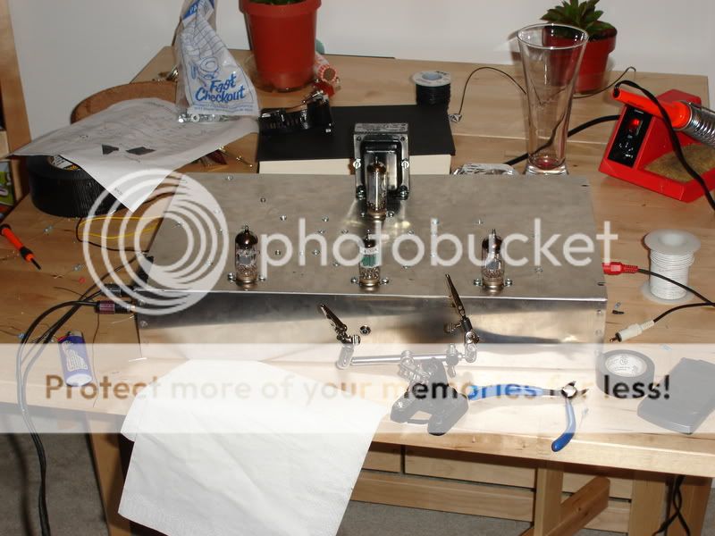
TIA, everybody here has been extremely helpful!
After my brief heater wiring confusion I've since been able to get the rest of 'scratch' up and running. So far so good: basic measurements look good, nothing over datasheet maximums. I've dropped the B+ to 278 VDC loaded.
First of two issues: Hum. I expected this. I originally laid the amp out before fully understanding how much that was going to effect the amount of hum injected into the signal lines. I have noticed that when I press on either a) the B+ transformer (exposed on top of chassis) or on the filament transformer (mounted on top plate, bottom side) that the hum decreases dramatically. I've attempted a good star ground and have noticed that if i move the input wires a bit while pressing on either tranformer that the hum nearly disappears.
Second issue: one channel significantly lower volume. I haven't measured everything with sound playing (hooked up the tt on a whim tonight) and am going to check for weird readings this weekend.
Quick pic:
TIA, everybody here has been extremely helpful!

- Status
- This old topic is closed. If you want to reopen this topic, contact a moderator using the "Report Post" button.
- Home
- Amplifiers
- Tubes / Valves
- 1st Project Heater Wiring