Hi everyone! I originally posted here
http://www.diyaudio.com/forums/showthread.php?s=&postid=1274416#post1274416
looking for some power supply recommendations. Since, I've decided that I would like to try a tube rectified PSU. Please see the above link and the links contained within for details on the project. I would really like to use a PCB for the project if at all possible. Any recommendations? I'm looking for something rather simple that would output +- 400 VDC.
")
+400 and +800 could be done more readily, though is much more dangerous than +/- 400.
I dont have any negative versions handy, but heres an illustration of a bridge rectifier done in tubes to show why Im a bit dubious of any simple project. 2 of the diodes cannot be a duodiode.
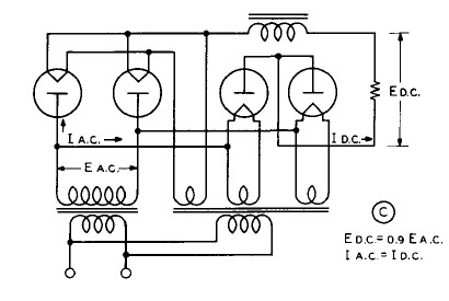
I dont have any negative versions handy, but heres an illustration of a bridge rectifier done in tubes to show why Im a bit dubious of any simple project. 2 of the diodes cannot be a duodiode.
here's a link:
http://headwize.com/projects/showfile.php?file=gilmore4_prj.htm
basically, +- 400 VDC, < 150 mA
Thanks again for the help!
http://headwize.com/projects/showfile.php?file=gilmore4_prj.htm
basically, +- 400 VDC, < 150 mA
Thanks again for the help!
Hi,
I have a PCB that can do hybrid or SS of what you need (though not bipolar all-tube).
Would it help?
Cheers!
luvdunhill said:I would really like to use a PCB for the project if at all possible. Any recommendations?
I have a PCB that can do hybrid or SS of what you need (though not bipolar all-tube).
Would it help?
Cheers!
Re: Re: Looking for a PCB / kit for a bipolar tube rectified PSU
maybe this would work, although again I'm not sure. You allow for using a full wave rectification. In my case, would using two diode tubes allow for more current that paralleling the 2 sections of a full-wave rectifier as a diode? I guess this is part of my confusion. If the full wave rectification would work, then yes two of your boards would work quite nicely!
Geek said:Hi,
I have a PCB that can do hybrid or SS of what you need (though not bipolar all-tube).
Would it help?
Cheers!
maybe this would work, although again I'm not sure. You allow for using a full wave rectification. In my case, would using two diode tubes allow for more current that paralleling the 2 sections of a full-wave rectifier as a diode? I guess this is part of my confusion. If the full wave rectification would work, then yes two of your boards would work quite nicely!
- Status
- This old topic is closed. If you want to reopen this topic, contact a moderator using the "Report Post" button.
- Home
- Amplifiers
- Tubes / Valves
- Looking for a PCB / kit for a bipolar tube rectified PSU