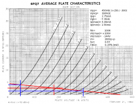
OK, got the plate curve thingee reasonably sussed for cathode bias etc etc. Now I want to use a tube in the front end of a gainclone as a buffer - tubelizer style. I can get a 5670 JAN NOS for $6.00 and they seem to be a useful item, but I'm hung up on calculating the cathode resistor. Is it the same value as the effective tube resistance at the applied voltage? 'Cos to my simple mind, that would give the right current through the tube and the unity gain. Or am I overcomplicating??? AAAAAAAAARGH! Assistance please - no, I don't want you to calculate it for me, i want to know how to do it! Cheers!
"How to calculate for cathode follower"
Loadlines.
In designing this cathode follower driver, start off calculating the Vpp. Since this needs a negative rail, the effective Vpp becomes 450Vdc. Knowing that the required current should be around 2.0mA, it looks like an Rk of 100K will do nicely, so add that loadline (from 4.5mA (Y) to 450V (X) ).
Since there needs to be -30Vdc at the cathode, and the plate is connected to a +150Vdc rail, the Vpk= 150 - (-30)= +180Vdc. Finding where the loadline crosses the 180Vdc line gives the Ipq, and extrapolate the Vgk to be ~7.4Vdc. Then read off the Ip(max) and Ip(min) from the loadline. Since the 100K resistor is connected to the cathode, you need to figure what the corresponding voltages are: Vrk= Ip * Rk. Since this is connected to a -300Vdc rail, the Vk= -300 + Vrk.
Once that's done, next figure out the gain. Since the Vgk extremes are 0V @ Ip(max), and the cathode is sitting at +106V, the grid must also be at 106V: Vi(+)= +106V, and -15V @ Ip(min), the grid needs to be 15V more negative than the cathode at -144V, so Vi(-)= -159V. The total Vi then becomes: Vi= 106 - (-159)= 265Vp-p. Vo= 106 - (-144)= 250Vp-p. Av= 250 / 265= 0.94.
Estimating distortion: Iave= (4.06 + 1.56) / 2= 2.81mA
Difference between Iave and Ipq: 2.81 - 2.75= 0.06mA
H2= 0.06 / (4.06 - 1.56)= 0.024 (2.4%) Not bad, but this applies only in the case of a common cathode stage. Since this is a common plate, the distortion is decreased by the inherent NFB.
Actual H2= (2.4)(15 / 265)= 0.14% The ratio of the common cathode input (15Vp-p) and the common plate input (265Vp-p) gives the feedback ratio. You take a fairly decent THD estimate and turn it into a really good one.
Attachments
- Status
- This old topic is closed. If you want to reopen this topic, contact a moderator using the "Report Post" button.

 Dammit! I mean, Thanx Miles, just what I needed, a long night of calculator, hot chocolate and thousands of bits of paper... No one ever said it would be easy huh. A very thorough yet compact lesson. I shall be back...