An idea for a partial feeback pentode amp using 6AU6's and 807's
Hi there,
I have an idea for a PP amp. I intend using microphone transformers as a front end step down and phase splitting stage. This would then feed a pentode configured 6AU6 (with regulated screen) LTP with CCS in the tail. This would then feed a pair of 807's in pentode mode with partial feedback to the grids.
This idea is based on the pentode amps which Gary Pimm developed.
Even with the front end step down of 9:1, the 6AU6 should have well enough gain to drive the 807's.
My question is what is a good operating point for the 6AU6, I have looked at a few datasheets and end up with a headache. I want a bias point of at least -3V , with a +B of between 250V and 350V.
Any experience greatly appreciated.
Shoog
Hi Shoog,
there are plenty of 6AU6 datasheets containing tons of tables of suggested operation points for audio duty. The manufacturers certainly knew why they suggested them. Just pick one that suits your gain, voltage swing and Zout demands.
Maybe you also could have a look at EF94 datasheets, which is the same tube, but European designation. When not developing for "special" situations, I just stick to the Lorenz EF94 table for RC-coupled gain stages.
As a more linear and capable alternative, EF80/6BX6 comes to mind, which is cheap and plenty (at least in Europe). I got stunning results and capabilities (extensively published elsewhere) using just a certain op point recommendation from the spec sheet.
Tom Schlangen
Re: An idea for a partial feeback pentode amp using 6AU6's and 807's
Hi Shoog,
why do you need a CCS in the LTP, for the phase inversion you have the input transformer?
Regards Andreas
Shoog said:Hi there,
I have an idea for a PP amp....feed a pentode configured 6AU6 (with regulated screen) LTP with CCS in the tail. ...Shoog
Hi Shoog,
why do you need a CCS in the LTP, for the phase inversion you have the input transformer?
Regards Andreas
Bandersnatch said:hey-Hey!!!,
If you go regulated voltage for the g2's of a LTP, make sure you ref it to the cathodes. LTP in both pentode and cascode with the upper g1, or g2 (in the case of the pentodes) didn't work anywhere near as well with the ref to ground.
cheers,
Douglas
Very useful tip - but sometimes somewhat difficult to do, as the common cathodes go up and down in unison with the input signal. Since a regulator is a feedback device, you may end up injecting distortion through G2.
OTOH, I have seen differential pentode LTPs in tube scopes and normally they don't bother with referencing the G2 supply to cathode, because the input signal is actually very small, so the change in Vg2-k is also very small. It is a form of feedback but since mu g1-g2 is so much smaller than effective pentode mu wrt plate, it is acceptable. Although input voltage swing is higher in audio amps compared to scopes (by 1-2 orders of magnitude!), it may still be fairly small (considerably less than 1%) compared to Vg2. Assuming the pentodes are not working to the extremes of their voltage swing, we can approximate that Ig2 of both pentodes together is fairly constant and will not upset the differential action of the LTP, adjusting the tail CCS higher to compensate for Ig2 of both tubes. If botha assumptions are correct, then investing in G2 regulation referenced to the common LTP cathodes may not provide a signifficant benefit compared to the cost.
There is a third soultuin, which is, however, only usable if three conditions are satisfied:
1) The amplifier uses single ended input
2) Fairly high NFB factors are used
3) The feedback is arranged for an inverting configuration, i.e. the input of the amp is the (-) input of the LTP and the (+) input is grounded, so the (-) input of the LTP is a virtual ground. This often implies lower input impedances.
Under these conditions, because the input of the LTP behaves as a virtual ground, the voltage swing on it is small, and so is, by consequence, the swing on the common cathode connection of the LTP. By extension, the variation in Vg2-K is also small compared to Vg2, the latter remains referenced to ground.
ilimzn said:
Very useful tip - but sometimes somewhat difficult to do, as the common cathodes go up and down in unison with the input signal. Since a regulator is a feedback device, you may end up injecting distortion through G2.
There is a third soultuin, which is, however, only usable if three conditions are satisfied:
1) The amplifier uses single ended input
2) Fairly high NFB factors are used
3) The feedback is arranged for an inverting configuration, i.e. the input of the amp is the (-) input of the LTP and the (+) input is grounded, so the (-) input of the LTP is a virtual ground. This often implies lower input impedances.
Under these conditions, because the input of the LTP behaves as a virtual ground, the voltage swing on it is small, and so is, by consequence, the swing on the common cathode connection of the LTP. By extension, the variation in Vg2-K is also small compared to Vg2, the latter remains referenced to ground.
Difficulty has Zero influence on importance.
Further, the seemingly small change offered by ref'ing g2 to cathode v. the ground makes important changes to the sonic signature IMO.
cheers,
Douglas
why do you need a CCS in the LTP, for the phase inversion you have the input transformer?
Good question.
Mainly because the presence of the Input transformer allows you easily to introduce the CCS without the need for a negative supply. The bottom of the input transformer can be referenced to the junction of the two 6AU6 cathodes and the top of the CCS. Each cathode has its own cathode bias resistor and the CCS can be a simple LM317. In this way the LTP with both sides driven by the input, should help to correct any slight imbalance introduced by the input transformer.
It really only constitutes a few extra components and its very unlikely to degrade the performance over them not been there. A sort of belt and braces approach.
Shoog
Shoog said:... In this way the LTP with both sides driven by the input, should help to correct any slight imbalance introduced by the input transformer. ...Shoog
Hi Shoog,
a very good idea, because often the capacitances to center tap are different (nonsymmetrical) in that transformers.
Regards Andreas
Hi Shoog,
In a pentode, anode current is not a linear function, too. But, Ia + Ig2 = Ik and the ratio between Ia and Ig2 stays reasonably constant in reasonable operation areas. No problem here with a CCS´d pentode differential pair if your loadline doesn´t enter the pentode knee area (sometimes also called "screen current takeover area" - think about it") ) too deep.
) too deep.
Hence, when setting the operation point/area for a pentode diff amp, CCS´d or not, plainly the same design rules have to be engaged as with a single ended pentode stage. In other words, just don´t put the operation point/area for the pentodes in a CCS´d diff pair where you wouldn´t put them for a plain, single ended pentode gain stage.
Tom Schlangen
Shoog said:The only fly in the ointment is the potentially none linear nature of the screen current.
Shoog
In a pentode, anode current is not a linear function, too. But, Ia + Ig2 = Ik and the ratio between Ia and Ig2 stays reasonably constant in reasonable operation areas. No problem here with a CCS´d pentode differential pair if your loadline doesn´t enter the pentode knee area (sometimes also called "screen current takeover area" - think about it
) too deep.Hence, when setting the operation point/area for a pentode diff amp, CCS´d or not, plainly the same design rules have to be engaged as with a single ended pentode stage. In other words, just don´t put the operation point/area for the pentodes in a CCS´d diff pair where you wouldn´t put them for a plain, single ended pentode gain stage.
Tom Schlangen
Re: An idea for a partial feeback pentode amp using 6AU6's and 807's
I have my doubts about this. Since the 807 requires a Vp= 22.5V in Class AB1, if you figure a sensitivity based on the usual 1.0Vrms, this gives: Vi= 1.4Vp. Divide that by 9, and that comes to a Vi= 0.15Vp at the input LTP. You'll need a gain of: 22.5 / 0.15= 150. Since this is a LTP, each 6AU6'll need a gain of 300, since you lose half your gain. That's asking one helluvalot form a 6AU6. Though this is a pretty good small signal VT, high gain ain't exactly its forte. And let's not forget that adding local NFB will increase the needed gain margin.
I'd see about reducing the ratio of the input xfmr.
Shoog said:Even with the front end step down of 9:1, the 6AU6 should have well enough gain to drive the 807's.
My question is what is a good operating point for the 6AU6, I have looked at a few datasheets and end up with a headache. I want a bias point of at least -3V , with a +B of between 250V and 350V.
I have my doubts about this. Since the 807 requires a Vp= 22.5V in Class AB1, if you figure a sensitivity based on the usual 1.0Vrms, this gives: Vi= 1.4Vp. Divide that by 9, and that comes to a Vi= 0.15Vp at the input LTP. You'll need a gain of: 22.5 / 0.15= 150. Since this is a LTP, each 6AU6'll need a gain of 300, since you lose half your gain. That's asking one helluvalot form a 6AU6. Though this is a pretty good small signal VT, high gain ain't exactly its forte. And let's not forget that adding local NFB will increase the needed gain margin.
I'd see about reducing the ratio of the input xfmr.
In a pentode, anode current is not a linear function, too. But, Ia + Ig2 = Ik and the ratio between Ia and Ig2 stays reasonably constant in reasonable operation areas. No problem here with a CCS´d pentode differential pair if your loadline doesn´t enter the pentode knee area (sometimes also called "screen current takeover area" - think about it ) too deep.
Hence, when setting the operation point/area for a pentode diff amp, CCS´d or not, plainly the same design rules have to be engaged as with a single ended pentode stage. In other words, just don´t put the operation point/area for the pentodes in a CCS´d diff pair where you wouldn´t put them for a plain, single ended pentode gain stage.
Tom Schlangen
Thats a useful heads up.
I have my doubts about this. Since the 807 requires a Vp= 22.5V in Class AB1, if you figure a sensitivity based on the usual 1.0Vrms, this gives: Vi= 1.4Vp. Divide that by 9, and that comes to a Vi= 0.15Vp at the input LTP. You'll need a gain of: 22.5 / 0.15= 150. Since this is a LTP, each 6AU6'll need a gain of 300, since you lose half your gain. That's asking one helluvalot form a 6AU6. Though this is a pretty good small signal VT, high gain ain't exactly its forte. And let's not forget that adding local NFB will increase the needed gain margin.
I'd see about reducing the ratio of the input xfmr.
Since I will be driving both of the input rather than just one, my understanding is that the halving doesn't apply - so I should be getting the full gain which I believe will be about 200. Of course things might not work out that nicely so I may have to choose another input transformer.
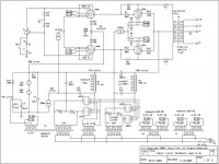
I will be running the amp in pure class A at lowish voltage. The operating point for the 807 I am thinking of is 250V plate and screen, which should give me a grid bias of -16V.
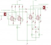
By the way heres a rough up of the concept.
Attachments
Tubes4e4 said:Hi Shoog,
In a pentode, anode current is not a linear function, too. But, Ia + Ig2 = Ik and the ratio between Ia and Ig2 stays reasonably constant in reasonable operation areas. No problem here with a CCS´d pentode differential pair if your loadline doesn´t enter the pentode knee area (sometimes also called "screen current takeover area" - think about it
Exactly my point.
But think about it, with plate to plate feedback this is actually almost a given, because the DC operating point stays the same and the AC loadline becomes steeper. Because the loadline becomes steeper, you are unlikely to go into low Vkp, which is where the knee is. In other words, it is the current that will vary, the voltage swing will be limited on the plate. Of course, one should then set up the DC operating point so it is as optimal as possible under AC conditions.
BTW I have a tube scope that uses a pair of EF184's in a LTP arrangement (resistor tail, no CCS semis back then...), it actually ties both G2 together to a common G2 supply, and it's not even decoupled to anything (it's a 20MHz scope) let alone the common cathodes. It is DC connected to a pair of ECC88 as followers, and to another LTP stage of ECC88, which is in fact connected in series with the whole first stage as far as the supply current is concerned. Odd arrangement but works marvelously. Obviously, they rely on the operating point being such that the sum of G2 currents of both sides of the LTP is very nearly constant - in this application it is possible amongst other things because the input voltage for the full required output swing is small, 50 or 100mV (don't have the thing in front of me at the moment). Of course, in the case of this amp design, the input and output swings will be larger (particulairly input), but my point is that at the first level of approximation even this simple technique works well.
I can't see any partial feedback in there.By the way heres a rough up of the concept.
I can't see any partial feedback in there.
You spotted that
I went to bed last night and a light went on - where was the feedback resistor. Well you know where its supposed to be and it will be in the worked up example.Shoog
- Status
- This old topic is closed. If you want to reopen this topic, contact a moderator using the "Report Post" button.
- Home
- Amplifiers
- Tubes / Valves
- An idea for a partial feedback pentode amp using 6AU6's and 807's