Hm. If we take parafeed setup with a CCS in an anode there wouldn't be AC signal either.
The other case is when a LED is in cathode circuit. Not quite a CCS, bur still ...
Am I missing anything?
Pawel
Indeed you are missing something.
With the CCS in the cathode it stops AC developing over the cathode and so imposses a fixed AC bias. It acts like an overwhelming amount of degenerative feedback (imagine what would happen if you put a one meg resistor in the cathode of a tube - but allowed the DC bias current to flow as normal ).
With the CCS in the anode it acts as a very stiff load (infact a perfect load) which the plate pumps up and down on. Since the plate is not the controlling element, the plate is free to move. The valve is allowed to realise all of its mu as gain rather than having it absorbed by the load resistor.
An LED is a fixed voltage reference with an extremely low impedance - in fact it is the complete opposite of a CCS.
Shoog
I have cross-coupled secondaries (center tapped to GND) to the bottom of the cathode resistor/bypass capacitor. This effectively forces the cathode AC voltages equal but opposite phase. The capacitor coupled cathodes make the cathode AC voltages equal in phase. I did not try the current generator/capacitor coupled cathodes yet. Now I am happy with the result. I use the original 560 ohm cathode resistors and 2200 uF bypass capacitors (shunted with 20 uF polystyrene). The lower end goes to the output transformer secondaries in opposite phase for both cathodes.Shoog said:The better way is to have independent CCS for each cathode and bypass them seperately. This can be turned into a differential pair by connecting the two caps cathodes together and referencing the node to a 1meg resistor, which then goes to earth. This unfortunately puts your caps in series and so effectively halves their value - so a cap of twice the size is needed.
Dear All,
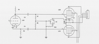
I am planning to mod my small pentode PP amp to use CCS(10M45, U5 in the schematic) replacing 200R resistor. Is it going to work and what kind of improvements can I expect, electronically and accoustically? The cathode current present is 72 mA at 14.3 V.
Thank you for your help.
Kay
I am planning to mod my small pentode PP amp to use CCS(10M45, U5 in the schematic) replacing 200R resistor. Is it going to work and what kind of improvements can I expect, electronically and accoustically? The cathode current present is 72 mA at 14.3 V.
Thank you for your help.
Kay
Attachments
I am planning to mod my small pentode PP amp to use CCS(10M45, U5 in the schematic) replacing 200R resistor. Is it going to work and what kind of improvements can I expect, electronically and accoustically? The cathode current present is 72 mA at 14.3 V.
Thank you for your help.
Yes it should work. Whats R8 for ??
Understand that you are restricting the amp to pure class A operation.
I would recommend using two CCS, one for each cathode. This will make hum a thing of the past, and should improve the quality of the bass.
If you use just one CCS, people have reported improvements in definition and bass. You will want a bias balancing network to get the most benefit. ala the Simple EL84 amp on "diyparadise" (you should find a link to this in this thread).
Of course if you do decide to use two CCS, I recommend setting them up as a fully differential pair as described previously.
Shoog
- Status
- This old topic is closed. If you want to reopen this topic, contact a moderator using the "Report Post" button.
