6H30
Hi,
Another nice Russky tube... if you can get it.
In theory that should not be a problem...what kind of circuit are you looking at?
Cheers,")
Hi,
Another nice Russky tube... if you can get it.
can i use one tube for both channel?
In theory that should not be a problem...what kind of circuit are you looking at?
Cheers,
6H30
Hi,
First of all,let's take a look at the datasheets:
6H30
The tube has the same pinout as the ECC88/6DJ8/6922.
So for use as an output stage in a DAC you will see that is very well suited,it takes higher plate voltage than the 6922 and will have lower output impedance too.
Circuitdiagrams using this type will be extremely rare since the tube itself is so hard to come by.
However you can use existing diagrams using the 6922 family of tubes and adapt these to take the 6H30.
Have a look at it while I try to unearth some schematics for you to try.
Cheers,
DAC.
Hi,
And I assume you want to replace the output stage with one based on this 6H30 ?
This is not for the beginning DIY though...if feel up to it let me know.
Cheers,
Hi,
its for a nos dac..
And I assume you want to replace the output stage with one based on this 6H30 ?
This is not for the beginning DIY though...if feel up to it let me know.
Cheers,
tube
hi frank,
i have no problem in building if to follow according to a circuit.
have look at the link that u have provided..thorsten circuit looks promising..guess i will follow his circuit...
so all i need is to build thorsten circuit and plug in a 6H30 tube in it..will there be any problem? ofcourse power supply is a different story..thorsten circuit uses one tube perchannel
>can i use my preamp 5687 circuit but uses 6h30 tube as dac tube output?
>thank u.
rgds,
tone
 Perugini made this design
POT.
Hi,
Provided it is a volume control.
What is this circuit for,anyway?
If it was meant for a DAC than it seems incomplete to me.
Cheers,
Hi,
There seems to be a small problem with the volume control connections...
Provided it is a volume control.
What is this circuit for,anyway?
If it was meant for a DAC than it seems incomplete to me.
Cheers,
6H30
Hi,
Jaap,
Can you tell us more about this circuit?
Where you found it and what it was designed for etc.,please?
Tone,
There is little point for you to start building anything at this stage yet.
All,
Is a de-emphasis always used on DACs?
I can't recall having seen one on the Sheldon Stokes design...if one is used,is it always the same passive circuit?
Obviously I am no Digital Wizzkid,
Hi,
Perugini made this design
Jaap,
Can you tell us more about this circuit?
Where you found it and what it was designed for etc.,please?
Tone,
There is little point for you to start building anything at this stage yet.
All,
Is a de-emphasis always used on DACs?
I can't recall having seen one on the Sheldon Stokes design...if one is used,is it always the same passive circuit?
Obviously I am no Digital Wizzkid,
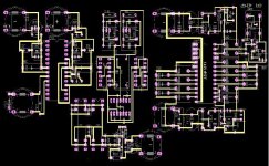
the perugini design
is indeed the analog stage after the dac chip and it uses the 6H30. This was the question.
The pot at the front is for the i/v conversion. After you have tried it for the right resistance you can exchange it for a normal resistor.
I have tried this design and it has a very neutral character, I had no complains, it works fine.
Jaap
Re: Volume control
Reinhard, can you explain that? I don't know what you mean by "current voltage conversion".
reinhard said:...the pot in the Perugini circuit is not a volume control, the resistance is used to make the Current Voltage conversion.
Reinhard, can you explain that? I don't know what you mean by "current voltage conversion".
Re: Re: Volume control
Joel, some DACs output a <i>current</i> that's proportional to the digital input. The TDA1541, PCM63 and a number of others are current output, whereas many others are voltage out. These Vout models use feedback around an opamp to do the I to V conversion, with the opamp being built onto the chip substrate.
In this case the pot, or a resistor will generate a voltage from the current output of the DAC, which is then amplified to a suitable level. Iout DACs put out less than 2mA for 0dBFSD.
HTH
Joel said:I don't know what you mean by "current voltage conversion".
Joel, some DACs output a <i>current</i> that's proportional to the digital input. The TDA1541, PCM63 and a number of others are current output, whereas many others are voltage out. These Vout models use feedback around an opamp to do the I to V conversion, with the opamp being built onto the chip substrate.
In this case the pot, or a resistor will generate a voltage from the current output of the DAC, which is then amplified to a suitable level. Iout DACs put out less than 2mA for 0dBFSD.
HTH
On my site you can find a dac tube output circuit using a pair of E182CC, these tube is the same as the 6H30 (russian code) an can be also substitute with the ECC99
ciao
Filippo
www.audiofanatic.it
ciao
Filippo
www.audiofanatic.it
- Status
- This old topic is closed. If you want to reopen this topic, contact a moderator using the "Report Post" button.
- Home
- Amplifiers
- Tubes / Valves
- 6h30 dac output circuit wanted..anyone?