I have convinced my brother he needs to get a tube amp, after hearing my completed Kennedy Audio / ST70.
I have a full set of iron from a ST70, the A-470 output xfrms and PA-060 power tranny. So, I'd like to build something within these constraints, and the following other preferences:
1. Readily available tubes in plentious supply and affordable. I currently use the 12AX7 into a 12AU7 LTP into EL34. All JJ tubes, and I'm happy with the results. I've also heard a lot of good things about the 6n6p, 6sn7, and ECC99.
2. Would like to avoid the 6922 and its variants; had bad JUJU with RF oscillations. Yeah, it was likely the builder, but if I'm building for someone else, I don't want too much troubleshooting.
3. No DHT's. This will be reserved for my personal use.
4. Build will be with non-exotic parts. ST70 iron really isn't worth much more than $5 coupling caps, IMO. However, I will be avoiding electrolytic caps in the PS.
5. I like the IXYS 10M45S current source; have had good results in the LTP, and I have a bunch.
6. Triode or UL really doesn't matter; if anything, I might make incorporate a switch.
7. If it matters, there will be a 80 Hz 6dB LP filter on the input, so I don't require thunderous bass out of the OPT's.
8. Input sensitivity maybe around a volt.
9. Speakers: actually don't know at this time, but it won't be horns, I can tell you that much. Most likely a simple 6" MTM. 15W will be more than enough, and if quality, 10W is okay, too.
10. SS rectification.
Sure, I can build the exact same thing, but that's not exactly the most fun, either. A little variation is good for the soul. But again, nothing experimental or ultra-daring.
Thanks for the suggestions.
Hi Zigzagflux,
I am not sure that I am qualified to comment as I am new to this myself, however - I had very similar ideas when I started my project and decided to go with a modified ST70.
Why not make a version of the ST70 with your own chassis. It seems to meet most of your criteria. You can upgrade the power supply caps (there is a kit if you like from triodelectronics) and point to point wire the rest. As far as the solid state rectification goes, the cap board kit has a solid state option or you could replace the GZ34 with a solid state version of this tube. I believe that a plug in solid state version of the GZ34 is available from radiodaze. There is also a version of the preamp (I think triode has this as well) replacing the 7199's with EF86 tubes. I believe there is also a 12AX7 version around somewhere as well.
Just a thought, cheers,
Rob
Rob11966 said:Why not make a version of the ST70 with your own chassis.
Sorry, I should have mentioned that. I have no chassis, no other parts, just the iron. So, yes, I will be building everything else from scratch. It surely won't look anything like a ST70.
In that respect, sky's the limit, as I have no real physical constraints.
Dude,
Let's look at the PSU 1st.
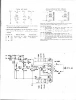
SS rectifying the PA-060's B+ winding is going to yield a high rail voltage. The extra Volts present an opportunity. Original ST70 power trafos are somewhat undersized. Ease the strain on the trafo by CLC filtering the B+ using 10 muF. in the 1st position followed by a Hammond 193M (10 H./300 mA.) choke. The smallish 1st cap. yields a large conduction angle and a cooler trafo. The large inductance takes a BITE out of the ripple and isolates the trafo from the remainder of the filter. BTW, a 'lytic is fine for the 10 muF. part, as it is not in the signal path. The B+ rail can be soft started by placing a CL150 NTC inrush current limiter between the diodes and the filter. Series connected pairs of UF4007s will rectify the B+. A RRSF will be used to keep SS diode switching noise out of the power trafo.
With all of the above, B+ still rates to be on the high side. Combination bias using a shared RC network in each channel under the EL34 cathodes consumes the remaining extra Volts. Combination bias allows the use of a single bias set pot. per channel and stabilizes the tubes against runaway.
The 5 VAC rectifier filament winding can be voltage multiplied to yield a negative rail that can power the LTP current sink and provide EL34 bias. The OEM bias tap gets tied off. The 2nd schematic here will do nicely. As drawn, a positive rail is created. Stand everything on its head for a negative rail. Use "noiseless" Schottky diodes in the multiplier.
Let's look at the PSU 1st.
SS rectifying the PA-060's B+ winding is going to yield a high rail voltage. The extra Volts present an opportunity. Original ST70 power trafos are somewhat undersized. Ease the strain on the trafo by CLC filtering the B+ using 10 muF. in the 1st position followed by a Hammond 193M (10 H./300 mA.) choke. The smallish 1st cap. yields a large conduction angle and a cooler trafo. The large inductance takes a BITE out of the ripple and isolates the trafo from the remainder of the filter. BTW, a 'lytic is fine for the 10 muF. part, as it is not in the signal path. The B+ rail can be soft started by placing a CL150 NTC inrush current limiter between the diodes and the filter. Series connected pairs of UF4007s will rectify the B+. A RRSF will be used to keep SS diode switching noise out of the power trafo.
With all of the above, B+ still rates to be on the high side. Combination bias using a shared RC network in each channel under the EL34 cathodes consumes the remaining extra Volts. Combination bias allows the use of a single bias set pot. per channel and stabilizes the tubes against runaway.
The 5 VAC rectifier filament winding can be voltage multiplied to yield a negative rail that can power the LTP current sink and provide EL34 bias. The OEM bias tap gets tied off. The 2nd schematic here will do nicely. As drawn, a positive rail is created. Stand everything on its head for a negative rail. Use "noiseless" Schottky diodes in the multiplier.
Okay.
So you are proposing a two stage amp (LTP as the first stage, cap coupled directly to the EL34). Otherwise, we wouldn't need the negative rail for the LTP, right? And is the EL34 the best choice? (No doubt, given availability and cost).
I'll be using PSUD for the power supply design. In fact, I had selected a 10uF followed by 4H to a 40uF cap, yielding 425V with 800mV AC ripple. I have no problem cranking up the L if necessary, though. I won't be using the C-354 choke.
Tangent: PSUD is a fantastic program, and doggone accurate if you get the transformer modeled right.
Forgive me, but what's RRSF? Reverse Recovery Soft Freugenschlager?
No problem with the rest of the power supply.
Next?
Forgive me, but what's RRSF?
RRSF = reverse recovery spike filter. Hop over to AA and search the Bottlehead Forum archive for RRSF.
I'll be using PSUD for the power supply design. In fact, I had selected a 10uF followed by 4H to a 40uF cap, yielding 425V with 800mV AC ripple. I have no problem cranking up the L if necessary, though.
The attached ST70 schematic shows 435 V. at the 1st filter capacitor. Even with a smaller 1st filter cap., SS rectification rates to yield something around 450 V. I know nada about simulation software. I'm from the read a data sheet, cut, and try "school".
So you are proposing a two stage amp (LTP as the first stage, cap coupled directly to the EL34). Otherwise, we wouldn't need the negative rail for the LTP, right?
I LIKE 2 stage amps. Unfortunately, no tube I'm aware of has the necessary HIGH mu and high gm to form a LTP that has sufficient gain to drive EL34s, with a 1 VRMS I/P. The 12AT7 splitter/driver in "El Cheapo" comes up short of being able to do the job. What I have in mind is the "El Cheapo" topology fronted by a common cathode 6SN7 section gain block that's outside the NFB loop. More than adequate linearity will be obtained by omitting the cathode resistor bypass capacitor.
ST70 iron really isn't worth much more than $5 coupling caps, IMO.
Dyna O/P "iron" was intended from the very beginning to be used with loop NFB. Loop NFB has a definite homogenizing effect. "Boutique" coupling caps. between the LTP and EL34s are (IMO) a waste of money. "Ordinary" film and foil parts get the job done. With that in mind, I recommend INEXPENSIVE 100 nF./630 WVDC Panasonic ECQP(U) caps. between splitter and "finals" and 330 KOhm grid to ground resistors on the EL34s.
BTW, since it's outside the NFB loop, a PIO cap. between the 6SN7 section and the LTP rates to be audible and might be beneficial.
Oh yeah, 150 Ohms and 220 muF. seem to be reasonable values for the EL34 bias networks.
Attachments
Unfortunately, no tube I'm aware of has the necessary HIGH mu and high gm to form a LTP that has sufficient gain to drive EL34s
6AQ4. D3a. There are probably more, but those are two I've worked with (tip o' the cap to Greg the Geek and Erik deBest for turning me on to the 6AQ4, Morgan Jones for the D3a). Each has a mu of 100 and outstanding open loop linearity, so are more than adequate to drive EL34 at 1V in.
That said, if it were my amp, I'd still do something with two stages like you said.
So here's my first iteration. Kind of took advice from both of you. If I can get the two stage amp to work, that would be the ticket.
I am working the 6AQ4 fairly hard at 210V, 6 mA, but that seemed to be the most linear range from the curves. If you have experience that says otherwise, let me know. Chose the load to be about twice the Rp.
I calculate an LTP gain around 46 with Zout of 8K. Input Z of EL34 is around 120pF, I think, so my F3 points are 3Hz and in excess of 100KHz.
A little stumped by the common cathode R for the output stage. I calculate 100mA total with about -30V of Vgk, so that comes to 300 ohms, not 150. Eli, you also mentioned using the negative rail for EL34 bias; are you proposing a combination of fixed and cathode bias? Fundamentally, if I'm developing a negative rail for the LTP anyway, it would seem fixed bias to be the bees knees for the output stage.
Unless you're adding the cathode R strictly for additional stabilization?
So far, so good?
Attachments
A little stumped by the common cathode R for the output stage. I calculate 100mA total with about -30V of Vgk, so that comes to 300 ohms, not 150. Eli, you also mentioned using the negative rail for EL34 bias; are you proposing a combination of fixed and cathode bias? Fundamentally, if I'm developing a negative rail for the LTP anyway, it would seem fixed bias to be the bees knees for the output stage.
I AM proposing combination bias. A 15 V. drop is excellent for consuming the extra B+ SS rectification yields. IMO, 100% cathode bias will unfavorably reduce the plate to cathode potential difference. Combination bias offers several advantages. The operating point is stabilized against runaway. A single bias pot. per channel is used. The shared RC network compensates for minor matching imperfections. Using adjustable bias allows for experimentation with the operating point.
I calculate an LTP gain around 46 with Zout of 8K.
The gain of a LTP is mu/2 into an INFINITE load. With a resistive load mu/4 is a fair approximation. A gain of 25 might be enough if the 2 VRMS O/P of a CDP was the I/P drive. With a 1 VRMS I/P, a gain of 25 is clearly insufficient to drive the EL34s and the NFB loop. The 3 stage circuit I previously suggested has plenty of gain and all the tubes (unlike the 6AQ4) are in production. The EH 6SN7 is decent. JJ's 12AT7 is OK and NOS Mullard is available at relatively reasonable prices. Given its distortion spectrum, high mu, and high gm, the 12AT7 is a superior choice for LTP service. The NET distortion spectrum of the amp is a pleasing "waterfall".
In this circuit, gain will be 32-35, depending on the tail current. Larger plate resistors and lower current will increase the gain but decrease the bandwidth. There's room for about 6-10dB of feedback if a standard 2-2.5VRMS (2.8-3.5V peak) input sensitivity is acceptable.
SY said:There's room for about 6-10dB of feedback if a standard 2-2.5VRMS (2.8-3.5V peak) input sensitivity is acceptable.
Therein may lie my problem. 0dB = 1.5 Vrms (2.1 peak) on his source. Of course most musical material will be 1V or less. Odds are he won't be building a linestage any time in the near future.
So I will visit the 3 stage idea, and give the driver plenty of headroom. I'll draft up a proposal for review (gives me practice with load lines and gain calculations).
Given a LTP with CCS tail, would the 12AT7 be the best choice if my first stage provides most of the gain? I would think a medium mu tube would be better suited, would have lower Rp, and therefore be a better driver? To pick some standard JJ's: ECC99, ECC802S, or 12AU7.
Never used the 6SN7, but always wanted to.
12AT7 is an excellent choice, as is the similar 6SL7. Lots of mu there. You could follow it with a 6SN7 driver. 12AU7 tends to be a lot less linear. I haven't used the ECC99, but that also looks like a good choice.
Another alternative is the classic Williamson input stage, with the coupling caps modified for better LF stability.
Another alternative is the classic Williamson input stage, with the coupling caps modified for better LF stability.
A good tube for a LTP should have high mu, high gm, and low Rp. The high gm is protection against slew limiting, which is always an issue in a circuit that includes loop NFB. The gm of a 12AT7 is 6 mA./V., while the gm of the 6SN7 is 2.5 mA./V. 12AT7 mu is 60, while 6SN7 mu is 20. The 6SN7 is better only in the Rp dept. and, at 11 KOhms, the 12AT7 isn't exactly bad.
Another consideration is NFB. A 12AT7 belongs inside a NFB loop, as some help with linearity is beneficial. OTOH, the 6SN7 is among the most linear voltage amplifying devices ever developed. An unbypassed cathode bias resistor is MORE than enough to hold distortion WAY down. If a 12AT7 is used for voltage gain and a 6SN7 is used as the LTP, a Mullard circuit, with its long global NFB loop, is (IMO) indicated. If a 6SN7 is used for voltage gain and a 12AT7 is used as the LTP, the short "El Cheapo" style non-global NFB loop, with its reduced vulnerabilty to phase shift trouble, can be employed.
Another consideration is NFB. A 12AT7 belongs inside a NFB loop, as some help with linearity is beneficial. OTOH, the 6SN7 is among the most linear voltage amplifying devices ever developed. An unbypassed cathode bias resistor is MORE than enough to hold distortion WAY down. If a 12AT7 is used for voltage gain and a 6SN7 is used as the LTP, a Mullard circuit, with its long global NFB loop, is (IMO) indicated. If a 6SN7 is used for voltage gain and a 12AT7 is used as the LTP, the short "El Cheapo" style non-global NFB loop, with its reduced vulnerabilty to phase shift trouble, can be employed.
Eli Duttman said:If a 6SN7 is used for voltage gain and a 12AT7 is used as the LTP, the short "El Cheapo" style non-global NFB loop, with its reduced vulnerabilty to phase shift trouble, can be employed.
Would this necessitate cap coupling the first stage to the LTP, in order to tie the feedback into the El Cheapo? My preference is as few cap couples as possible; but then again, if it's outside GNFB, it shouldn't be that big of an issue?
With the El Cheapo, I don't see any HF compensation. Where would one typically apply it, with a cap across the feedback resistor?
Finally, I am thinking about the possibility of using the output stage Bob McIntyre used in his "Modifying Mighty Mouse" in Audio Xpress. CCS in each cathode, with a motor run between the cathodes. Seems like a neat idea, and my brother would not have to concern himself with adjusting bias or tube matching (he's not too electrically minded). Anyone have experience with this, or is it an idea worth trying? I can get 435V for a B+, so my EL34 will be running around 50mA and 400V.
Thanks for all the help. !
Would this necessitate cap coupling the first stage to the LTP, in order to tie the feedback into the El Cheapo? My preference is as few cap couples as possible; but then again, if it's outside GNFB, it shouldn't be that big of an issue?
Yes, a cap. is needed between the voltage gain block and the LTP. As you pointed out, this cap. is outside the NFB loop. IMO, that makes this THE spot to use a PIO part, should you so choose.
BTW, look at the LTP Mullard circuit and you'll find the cap. coupling the non-inverting grid of the LTP to ground. In this case, the cap. IS inside the NFB loop.
I agree with you that holding phase shifts down to the absolute minimum inside NFB loops is necessary. In "El Cheapo" only the LTP to "finals" coupling caps. and cathode resistor bypass cap. are present inside the loop. In addition, non-inductive meter matched Carbon comp. parts are called for as NFB resistors.
With the El Cheapo, I don't see any HF compensation. Where would one typically apply it, with a cap across the feedback resistor?
"El Cheapo" does have HF compensation. It comes from using inductive WW load resistors as the LTP loads. LTP gain increases slightly with rising freq. The idea is to reduce the HF error correction signal. An added refinement (discussed here) is to short the NFB loop out above some arbitrary freq. and allow the natural roll off of the O/P trafo to set in.
Finally, I am thinking about the possibility of using the output stage Bob McIntyre used in his "Modifying Mighty Mouse" in Audio Xpress. CCS in each cathode, with a motor run between the cathodes. Seems like a neat idea, and my brother would not have to concern himself with adjusting bias or tube matching (he's not too electrically minded). Anyone have experience with this, or is it an idea worth trying? I can get 435V for a B+, so my EL34 will be running around 50mA and 400V.
Implicit in the use of CCSes under the EL34 cathodes is Class "A" operation, which may or may not be a good thing. If your brother is too klutzy to rebias 4X per year, consider using Mullard's self biasing scheme.
Eli Duttman said:Implicit in the use of CCSes under the EL34 cathodes is Class "A" operation, which may or may not be a good thing.
Yes, and I just finished reading SY's Red Light District article from DIYMAG, where he says basically the same thing. Could someone clarify the deficiency? At face value this seemed like a great method.
Here's an attempt. Tried to be thorough with the analysis.
Sorry about the image quality. I'll try to get a better scan tomorrow.
Basically, I thought I'd give the ECC99 a try for its low Rp, but the linearity: I guess we'll see.
Open loop gain seems reasonable. Biggest problem I see is the power transformer capacity. I might have to go with a separate xfmr for the driver stages. We'll see.
Problems? Is this going backward?
Attachments
At face value this seemed like a great method.
And as long as you never clip the amp, it is. Unfortunately, clip happens.
- Status
- This old topic is closed. If you want to reopen this topic, contact a moderator using the "Report Post" button.
- Home
- Amplifiers
- Tubes / Valves
- ST70 iron recommendations please