why 200 V
The voltage drop across the tube is chosen to maximize the available voltage swing.
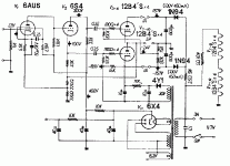
The basic idea is to have the plate resistor drop 1/4 of the supply voltage, the tube drop 1/2 the voltage, and the cathode resistor drop the final 1/4 of the voltage. So with the input to the phase splitter centered at approximately the same voltage as the cathode (within a few volts ) then it can theoretically swing 1/4 of the supply voltage in either direction without cutting off the tube or having the plate voltage less than the cathode voltage.
So in the case of a 400 V supply as shown in your schematic there is indeed 200 V across the tube, as you mention.
For a 300 V Supply you would chose to have 150 V across the tube, and 75 volts across the plate resistor and across the cathode resistor.
To do this you may need to adjust the 6AU6 resistors to give about 75 V at the plate and also to hit the bias point of lowest distortion.
Some people would also lower the 33k ohm resistors on the phase splitter to say 22K to keep the bias current through that tube about the same.
- Status
- This old topic is closed. If you want to reopen this topic, contact a moderator using the "Report Post" button.

