Hello all good ppl!
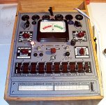
I've almost finished electronically restoring this old EMC 200 (transconductance) tube tester. Will work of enclosure woodwork later.
The problem I have here is that I am having hard time trying to locate any instructional material on this unit. I kind of can figure out some action on how to use it based on my previous experience but it is pretty hard guessing work and it would help a lot if I could find any material on this machine.
If anybody could give me a lead or a tip It would be greatly appreciated.
Maybe there's some spot on the internet that is hidden from searches or something? I almost gave up trying to find any material.
Thanks in advance
/respects
**********
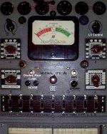
I am attaching a photo of the tester on my bench:
I've almost finished electronically restoring this old EMC 200 (transconductance) tube tester. Will work of enclosure woodwork later.
The problem I have here is that I am having hard time trying to locate any instructional material on this unit. I kind of can figure out some action on how to use it based on my previous experience but it is pretty hard guessing work and it would help a lot if I could find any material on this machine.
If anybody could give me a lead or a tip It would be greatly appreciated.
Maybe there's some spot on the internet that is hidden from searches or something? I almost gave up trying to find any material.
Thanks in advance
/respects
**********
I am attaching a photo of the tester on my bench:
Attachments
Bama doesn't have a manual for the 200, but has manuals for several other models. Perhaps there is something useful in them:
http://bama.sbc.edu/emc.htm
http://bama.sbc.edu/emc.htm
Couple notes here.
First of all SORRY for double post here. I though somthing went wrong when posting the thread. Had no idea about "under moderation" period.
*********
also, I have found info about 205 model, which is similar unit but 'emission type'. It gives me some starting point ideas on how to use 200.
found here: http://www.jogis-roehrenbude.de/Roe-Pruefer.htm
Kevin, thanks a ton for trying to help. Yeah, I had been at bama and got those too. Actually I have this mirror page: http://bama.edebris.com/manuals/ , as I get "not found" all the time at http://bama.sbc.edu
Yep. I went through those. 205 unit is as close as it gets I guess. I thoguht it would be somewhat easier to figure the unit out without manual, but not so. It's a puzzleethermion said:The 211 & 213 at bama are from the 1960s. Your 200 is 1946. Probably not much help in those manuals.
Might try some of the vintage radio forums, or track down a copy from one of the online dealers.
Try and see what's gonna happen is not a good idea in this situation. I'll keep trying to find something. I have not seen that manual anywhere for sale either.
I may end up to completely reverse-engineering the unit ...  hope not
Hi Dr. Zee,
One thought that comes to mind is that all of the settings required to use the tester (at least for the types then available) should be in the roll chart.
If you can post a good picture of the entire chart showing a type listing we might be able to decipher how to set up the tester to actually test tubes. Worst case just type the entries from an entire row..
I have the manuals for my Hickok, but have hardly ever had to refer to them - the charts should be fairly intuitive once you are familiar with them. (Now the Hickok charts might have been better than the EMC charts, but I'll bet there is not that much difference.)
Kevin, thanks a bunch again.
I've made some extra photos. Am posting them in the following posts.
Any thought or an idea would be a help. As I kind of figured that it is not going to be a simple tast to simply "reverse engineer" this thing. It may not look like a big deal, but actually to try to catch the principle(s) behind this unit with no leads is pretty damn challenging, well, for me anyway.
I've done pretty much everything that looked like had to be done as bringing this unit to life. Replaced couple resistors, caps, cleand all the switched and pots in and out etc. I've powered it up. Got to the point of setting the L.V. level. All looks and smells good. But this is it. I have not tried yet to actually insert a tube, because I don't want to get in trouble before I get some idea about what I am doing.
My current guess is , that all the switches should be in "K" position. Then you start settings from there, but the order of actions and what I should and should not switch etc ... all bunch of unknowns for me.
OK, here we go with photos.
I've made some extra photos. Am posting them in the following posts.
Any thought or an idea would be a help. As I kind of figured that it is not going to be a simple tast to simply "reverse engineer" this thing. It may not look like a big deal, but actually to try to catch the principle(s) behind this unit with no leads is pretty damn challenging, well, for me anyway.
I've done pretty much everything that looked like had to be done as bringing this unit to life. Replaced couple resistors, caps, cleand all the switched and pots in and out etc. I've powered it up. Got to the point of setting the L.V. level. All looks and smells good
. But this is it. I have not tried yet to actually insert a tube, because I don't want to get in trouble before I get some idea about what I am doing.My current guess is , that all the switches should be in "K" position. Then you start settings from there, but the order of actions and what I should and should not switch etc ... all bunch of unknowns for me.
OK, here we go with photos.

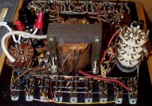
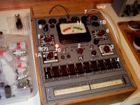
inside stuff
(special / normal "N/S switch is under the transformer) actually to see anything or try to figure out the connections there I would have to remove the trnsformer and this is actually a big freakin' deal, simply because the way it is assembled, and I can not move the transformer without disconnecting all (or at least half of the leads) . I don't want to do that.
(special / normal "N/S switch is under the transformer) actually to see anything or try to figure out the connections there I would have to remove the trnsformer and this is actually a big freakin' deal, simply because the way it is assembled, and I can not move the transformer without disconnecting all (or at least half of the leads) . I don't want to do that.
Attachments
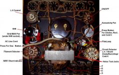
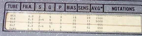
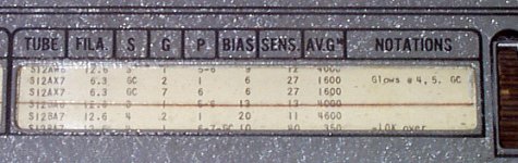
On the roll chart referring from left to right you see FIL - set the filament voltage control to the filament voltage indicated.
Note that the row of switches above the chart are marked S G P K and each one has a pin number underneath it. There are 8 + GC. (GC stands for grid cap.)
Next on the chart you will see S, set the switch with corresponding number indicated in this column to S, if there is more than one number set all indicated numbers to this position.
Next is G, set switch with the corresponding number to G.
Next is P, again set switch with the corresponding number to P.
I believe that any switch pin number not mentioned in the chart should be set to K.
Bias value is next, read the number and set the bias control to the value listed.
Sensitivity is next, read the number and set the sensitivity control to the value listed.
AVGM is the nominal value you should read off of the meter. I'm assuming in most cases if you are in the green the tube will be ok.
I did not see any specific settings for filament pins so the tube types that can be tested are specifically limited to the types listed in the roll chart as I assume the filament connections are probably hard wired.
Pay special attention to the Notation section as there are likely in some cases to be additional information to assist in interpreting the result. This should also provide some additional setting information where required.
Circuit Selector:
**LV position on the circuit selector is for setting Line Voltage using the LV control - set this using the meter which is marked at the proper setting for line voltage. Do this before testing anything and adjust each time you use the tester or change tube types under test. Check this again with the tube installed and filament warm, adjust as necessary - with power tubes and rectifiers you might need to tweak this again before reading the final value. **
Rectifier - use this position to test rectifier diodes, press switch marked rectifier and cold K test - check meter reading. Do not hold longer than necessary to get the reading.
Cold K (Cold Cathode) use for testing gas regulator tubes like the OA2, VR75, VR150 etc..
Gm - this is the position to use to measure the transconductance
Shorts - interelectrode short test, use with labeled button, check notations. If there is a short the neon lamp will light. This may not be a reliable indication of shorts.
Try it only with tube types listed in the chart. Insert the tube only after the initial settings have been made.
This might not explain how to use all of the features in the tester, but it should allow you to get started. Hopefully I have not made too many errors in explaining how the tester works.
Nice tester by the way..
Kevin! Thanks a ton. You're the man.
Now, what do you think the 1-8/GC switches should be as "starting point"...or the position of switches that are not in the chart for the tube? I thought it is "K". Or does it matter what position the switches are if they are not mentioned in the chart for the tube under the test? Is it a "stupid question" ...heh heh
The thing is , that this is THE QUESTION for me and that is why I said to myself: "I better try to figure it out befor inserting any tube here".
Now there is another "mystery" for me here. After I set everything as in the chart and check/set L.V. control and then so I am ready to insert the tube. So I suppose I would first have to go through "Short" test. So I switch from L.V. to "SH" and then what? What your guess would be. ? Just to see if the short-neon glows or do you think I should go through switching some switches, let's say to "S" position one by one and then return to "K"?
OK, Kevin, if my "questions" gives you headache, then just ignore it
I've found another photo I've made in the past while working on cleaning etc... that shows the ciruit selector, attachine bellow:
Attachments
Kevin, yeah, speaking of "noise". Any idea what phones can I try there? Do I need to shop eBay for some "special" phones from 50s Or what other options. Or is it even worth of trouble, meaning , practicality of "noise test"?
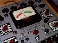
here's another photo closeup of the meter
Or what other options. Or is it even worth of trouble, meaning , practicality of "noise test"?here's another photo closeup of the meter
Attachments
ok
armed by Kevin's wisdom I've got brave to go for it and try testing something.
So far things doing well, no smoke no fire
I am just going to sort of sum up step by step of what I've done, not to be taken as "instructions", but at least it's a start.
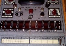
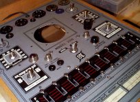
See attached photo. (The example is there 12AU7 (I've tested few of those)
Steps:
1(A). All 1-8/GC switches in "K" position, no set up. First just powered up the unit. Circuit Selector in L.V. position.
1(B). After few seconds of heating up , set up L.V. control to match the Line Level mark on the meter. Turned the unit OFF.
*****
2. Set N/S switch to "Special" as per chart for 12AU7
3. Set Filament selector to 6.3 as per chart for 12AU7
4. Set switches "S" - GC, "G"- 2, "P" - 1 as per chart for 12AU7 (first section)
5. Set Sensetivity Pot as per chart for 12AU7
6. Set Grid Bias as per chart for 12AU7
7. Insert the tube
8. Turn the unit "ON". Note: the Circuit Selector is in "L.V." position. Check L.V. on the meter.
Also as I turn the unit "ON" the under the test tub's filament is lightening up, so is "on"
9. Give a few seconds for the tube to heat up. Set the Circuit Switch to "SH" position. Now, here's a big QUESTION for me. Is it it? Just to see if the Neon glows or do I have to do some switching to do to check for shorts.
(As I understand before moving to "Quality Test" it is a good idea to make sure that the tube is OK for "shorts". So this is a grey area for me at the moment how to 'correctly' pass this sep on this tester.
The tubes I was testing were previousely tested on my Acurate Instrumets 257 emission type tester, so I assume that they are all OK, and so I moved on...)
10. Set Circuit Selector to AMP. position.
11. Read the meter.
I've got vary results (readings) on this tester when testing tubes, that were before tested "GOOD" on emission tester. Also readings on the meter were rather "High" comparing to what I would expect according to chart notes. As per chart for 12AU7 it is noted: AV.Gm-2000, my reading were somewhat between 2500 and 3000 (far right meter position).
So I am not sure what to make out of this. I guess interpreting the results othere than "good/bad" is the whole different story
armed by Kevin's wisdom I've got brave to go for it and try testing something.
So far things doing well, no smoke no fire
I am just going to sort of sum up step by step of what I've done, not to be taken as "instructions", but at least it's a start.
See attached photo. (The example is there 12AU7 (I've tested few of those)
Steps:
1(A). All 1-8/GC switches in "K" position, no set up. First just powered up the unit. Circuit Selector in L.V. position.
1(B). After few seconds of heating up , set up L.V. control to match the Line Level mark on the meter. Turned the unit OFF.
*****
2. Set N/S switch to "Special" as per chart for 12AU7
3. Set Filament selector to 6.3 as per chart for 12AU7
4. Set switches "S" - GC, "G"- 2, "P" - 1 as per chart for 12AU7 (first section)
5. Set Sensetivity Pot as per chart for 12AU7
6. Set Grid Bias as per chart for 12AU7
7. Insert the tube
8. Turn the unit "ON". Note: the Circuit Selector is in "L.V." position. Check L.V. on the meter.
Also as I turn the unit "ON" the under the test tub's filament is lightening up, so is "on"
9. Give a few seconds for the tube to heat up. Set the Circuit Switch to "SH" position. Now, here's a big QUESTION for me. Is it it? Just to see if the Neon glows or do I have to do some switching to do to check for shorts.
(As I understand before moving to "Quality Test" it is a good idea to make sure that the tube is OK for "shorts". So this is a grey area for me at the moment how to 'correctly' pass this sep on this tester.
The tubes I was testing were previousely tested on my Acurate Instrumets 257 emission type tester, so I assume that they are all OK, and so I moved on...)
10. Set Circuit Selector to AMP. position.
11. Read the meter.
I've got vary results (readings) on this tester when testing tubes, that were before tested "GOOD" on emission tester. Also readings on the meter were rather "High" comparing to what I would expect according to chart notes. As per chart for 12AU7 it is noted: AV.Gm-2000, my reading were somewhat between 2500 and 3000 (far right meter position).
So I am not sure what to make out of this. I guess interpreting the results othere than "good/bad" is the whole different story
Attachments
- Status
- This old topic is closed. If you want to reopen this topic, contact a moderator using the "Report Post" button.
- Home
- Design & Build
- Equipment & Tools
- EMC Model 200 Tube Tester Any Info Pls