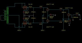
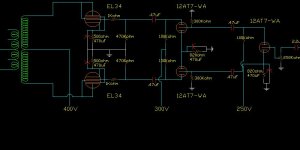
Hi, this is my first post. I have lots of questions. I decided last christmas to design and build a tube amplifier for reasons I dont even remember. Let me get this started by stating that in this schematic I have decided to use 12AT7-WA. I also need someone to check this schematic who knows much more knowledge than I contain at this moment. I have talked to my professor last semester and said there is a load line method to determine some of the resistor values in this circuit, has anyone done this for either one of these tubes, keep in mind I would like to use the 12AT7-WA? Any criticism or input on what I am doing here would be, well, very helpful.
Attachments
Looks like reasonable approach for a guitar amplifier application, but this circuit is rarely used for stereo amplifiers, it will work particularly with the 12AT7WA but available loop gain will not be sufficient for good linearity closed loop, for this reason damping factor with the pentode connection is likely to be low as well. AC balance in this type of phase inverter can be a problem at high frequencies as well.
What is the intended application for this amplifier? Do you need this much power or could you settle for about 15W and use EL84/6BQ5 - results are likely to be better with this topology.
Any particular reason why you choose pentode connection over UL or triode?
Others will weigh in soon with more relevant comments and many things I have missed.
I have intended to use it for a hi-fi; I realize that these tubes are generaly used for guitar. Also, I already have the tubes which makes it apeal to me more. Also I dont want anything too complex as this is my first to try to have two channels in one package. I will be driving a pair of JBL L-88 or 33 or I cant remember their model number right off hand but much like the L-100's. Also choice not for UL is I dont have that type of output transformer. Choice not for triode the power transformer I have currently is a 450-0-450 thordarson. I am trying not to spend to much on this, so using the existing major components is what I am after per the 12at7 choice and the el34 choice. So your comment on a different tube however a very good suggestion, and if i did not already have the el34 would probably take that road. I also agree with the feedback statement but I do not really know how to adjust that to get what it needs.
Build it for a start. The EL34's will have a long life as they are conservatively run.
The performance of the power supply is important in this pentode configuration esp for anode/screen grids (g2) as the no sig to max sig current change is quite high. The feed to the screen grids should go through a 470R resistor to a well stabilised 300V. This 300V should come up with the anode voltage or after to avoid excessive current damaging the screen grids.
Despite kevinkr comments on open loop gains, I'm finding that some amps actually sound more dynamically pleasing when the front end (1st stage) gain is modest which requires higher signal input level and lower global nfb resistor. In otherwords when the 1st stage is a standard pentode stage with perhaps 40dB gain before global nfb feedback applied there is some performance advantage by strapping it as a triode which usually gives around 25dB. I'm finding that it is easier to get better control of 10Khz square wave tests i.e less ringing and overshoot created by output transformers.
This is tricky, and in your design there is alot of merit in adopting a simplest p-p and it should delight you. Remember if it howls on first test, reverse secondary on o/p transformer and reconnect nfb loop.
richj
I agree, go ahead and try it. However, you might get parasitic oscillations without grid stopper resistors on the EL34. I would use 4.7k stoppers on the control grids and 150 ohm on the screens, soldered as close as possible with very short leads to the respectgive pins. They need to be non-inductive resistors (definitely not wire wound), preferably carbon if you have them.
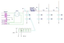
I am very sorry I did not post that in my orignal section. I thought at first that there would be more work to do on the signal amplification part of the circuit. In this picture you will see that above the inductor I have written in that I have two inductors in serries. The main reason I have done this is to get the voltage down to a reasonable voltage. I also mis spoke about the power transformer that I am using as it is a 400-0-400 as listed in 1949 by Thordarson. I also am going to assume that each set of EL34's will pull about 70ma at idle and the grids will pull about 10ma a piece. The 12at7's I am not sure about idle current draw but I would think about 10ma per triode. So to add that up 140ma for the EL34's plates, 20ma for the EL34's grids, and 20ma for the 12at7's for a grand total of 190ma or there abouts. I think that sould be the idle current draw. I am not sure that the voltages I actually have written in on this picture are entirely correct. So the DC voltage befor the inductors should be 425V, after the inductors roughly 368Vdc(193M DC resistance is about 50 ohms plush 250 ohms from the other transformer)throught the 1.6kohm next voltage should be about 304 and the plate voltage for the triodes should be through a 5kohm and the voltage on that should be 200Volts or so seems low but that is my circuit analysis for this section.
Attachments
The 5U4 will give peak switch-on DC about 550V+ before power tubes warm up, so be careful. I'm suspicious of the screen grid voltage fed from a high value resistive source. This voltage will fall on signal transients and create distortion. The main thing is get amp working then look at improvements.
richj
richj
Couple of suggestions:
Get the free PSUD program and play with it if you need to make any power supply modifications. Or play with it anyway, it's very easy in intuitive and will give you a good sense of what's going on in the power supply. http://www.duncanamps.com/tdslpe/download.html
This site is not the state of the art in terms of layout and ease of use but is chock full of good tube info. It has a very nice tutorial on loadlines. http://members.aol.com/sbench101/
If you want to go a step further, and to safe SY the trouble of suggesting it, Morgan Jone's books, Valve Amplifiers, and Building Valve Amplifiers.
Sheldon
Thanks for all of those suggestions for sites to go and check out, and I will go check these out and see what I can find. I do have an old electronics book copywritten in 59' I believe, but I have not spent too much time sifting through it. I did have a chance to fire it up last night at about 10 o'clock or so. I fired it up and once it stabalized the DC voltage off of the rectifier was 400V, then the B+ voltage was 355, the grid voltage leveled off at 298 and the plate voltage for the triodes was at 244. I beileve those to be very close to what I spesified on the first schematic I posted. Those voltages are with only Hammond choke in the circuit. Also I did not tie in the negative feedback due to time constraints last ight. With the voltages being so close I decied to hook up some music to it and see what it did. One channel (we will call it left), the left channel sounded great, a little ringy but I think that is because of the source I was using, my computer because I did not have my CD deck or anything hooked up at the moment. The right channel did not sound anywhere close to as good, it was spitting noise and the music alternatly. About the time I made that novel discovery I notice one of the cathode bypass resistors was looking pretty warm. It was very warm, much warmer than the rest of the bypass resistors. I am not entirely sure what that means but I suspect a bad tube. I am not for sure on that at the moment. This evening I will probably flip flop the tubes from left to right and visa versa and see what happens. The resistor statement across each capacitor in the power circuit, that is right, I should put a resistor across each one to ensure the equal distribution of voltage. Tonight I will put a 300 kohm resistor across each one. I have attached a picture of what I had hooked up last night and an arrow pointing to the problem resistor. I need some help to figure out why and what that means
Attachments
Warm cathode bias resistor is probably a sign of a bad output tube or alternately an oscillating output tube. The schematic is illegible on my monitor, so you may already have grid stopper resistors, if not install 1K in series with the pin right at pin 5 of each EL34.
EL34 screens sometime benefit from bypassing to ground with a small 0.01uF film cap right at pin4 when operated in pentode mode. (Kills vhf oscillations)
EL34 screens sometime benefit from bypassing to ground with a small 0.01uF film cap right at pin4 when operated in pentode mode. (Kills vhf oscillations)
Ok, I will try both of those to see if that fixes the issue. Would a .0022uf polyester film cap be sufficient for the pin 4 bypass? I also measured the voltage with respect to ground on pin 8 & 1, on the right channel(one with the problem) and it is -60 some odd volts on one and -50 some odd volts on the other one. With p=v^2/r we are well above the rated power of those resistors. The left channel measure in on both tubes at about -21 volts. My question, probably not a very good one, but why would the left channel which is identicle work just fine but the other one just 6 inches to the right have such a terrible problem. I am also working on the assumtion that the output tubes are fine, I actually first thought it might be that but I swapped tubes from the left and right channels and it did not seem to effect the voltage or the seemingly singular problem, the left channel worked and worked well and the right still the same problem. Thanks again for the input and I will let ya'll know what I come to find out.
So, I have not had much time lately to mess with my amplifier. I did have this question. Someone spoke of problems with high frequencies not coming through with the way I was getting my phase inversion (the highs do ring a bit in the side that works); what if I were to add a triode stage before my circuit and strap the EL34 as a triode as someone suggested earlier? I do have plenty of 12at7's so adding an extra tube would not be a big deal. If someone would check this, I really just copied my first stage and used the same cathode bypass. I looked on the data sheet for the EL34 and it says to tie grid2 to anode and g3 should be at 0v which means I should tie it directly to ground? (I have it tied to the cathode) Also I am not sure how to calculate what negative feedback should be used, anyone have any suggestions on how to go about that? Well, thanks for any input that has been put in already and more would be much appreciated.
From the pic, it looks like youv'e got no grid leaks on the 12AT7 driver stage. That will account for alot of trouble.
If you use the EL34 in triode (mode as you show) then Rcathode = 470R per tube at B+400V. You don't mention the characteristic imp of the output tranny. Anywhere between 6-10K a-a ? You should be looking for 15W output power.
richj
If you use the EL34 in triode (mode as you show) then Rcathode = 470R per tube at B+400V. You don't mention the characteristic imp of the output tranny. Anywhere between 6-10K a-a ? You should be looking for 15W output power.
richj
Will, the 500ohm resistors be sufficient? Also I have some 300kohm resistors lying around or even 100kohm if that would be better for the grid leak? Also the output transformer, funny you ask. I got a matched pair from a guy out of some old Stromberg Carlson equipment, I don’t really know much about them, don’t know what tubes were used with it. I do know their production date. They were stamped in '53 I think. I will get a picture of them this evening to see if anyone knows anything about them.
Attachments
J_Hart_14 said:Will, the 500ohm resistors be sufficient? Also I have some 300kohm resistors lying around or even 100kohm if that would be better for the grid leak?
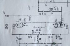
300K for grid leak absolute min but not lower. I can't make out the lowerhalf phasesplitter. . If you are using a common cathode resistor and a decoupling cap then it's not LTP as the signal isn't being transferred via cathodes. If you want to use paraphase then as no nfb is used then the front end gain will be too high. Where is the other phase getting it's signal from ? On my screen it looks like ground. If its grounded via 0.47uF then ?? can't follow diagram.
I've enclosed a pic of a common configuration used......note the 1st stage is connected directly to the grid of 2nd stage and the undecoupled cathode resistor . Do the math first if you want to change front end to fit.
The 500ohm cathode resistors will underrun the o/p stage.
hope this helps. It pays to get the right values.
richj
Attachments
- Status
- This old topic is closed. If you want to reopen this topic, contact a moderator using the "Report Post" button.
- Home
- Amplifiers
- Tubes / Valves
- Stereo EL34 amplifier