Hey Spas
Did you check out this thread ?
http://www.diyaudio.com/forums/showthread.php?s=&threadid=60438&highlight=
The circuit from PRR seems easy to build
Did you check out this thread ?
http://www.diyaudio.com/forums/showthread.php?s=&threadid=60438&highlight=
The circuit from PRR seems easy to build
OTL amps are not really projects for people who haven't worked with tube circuits before. If one tube decides to short you better have fast blow fuses because your speakers won't last very long.
But here is a circuit that is simple and does not need a split power supply.
But here is a circuit that is simple and does not need a split power supply.
Attachments
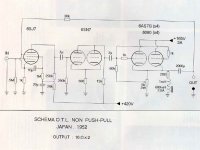
astouffer said:............. here is a circuit that is simple and does not need a split power supply.
Hi.
As I have posted in other OTL threads:-
although this circuit does not have a transformer, it is choke loaded and therefore is not really 'OTL', as the performance depends on the choke.
Andy
quinnling said:Hey Spas
Did you check out this thread ?
http://www.diyaudio.com/forums/showthread.php?s=&threadid=60438&highlight=
The circuit from PRR seems easy to build
That DOES seem easy to build. 3W distorted with one tube into an 8-ohm load should mean that I'll get at least a good 30W with four tubes into a 64-ohm load. I wonder if I could use the other half of the 12AX7 to get a bit of gain?
astouffer said:OTL amps are not really projects for people who haven't worked with tube circuits before. If one tube decides to short you better have fast blow fuses because your speakers won't last very long.
But here is a circuit that is simple and does not need a split power supply.
That's a single-ended amp. It's not going to be nearly powerful enough for my purposes.
On the subject of speaker protection, I'm not stupid - the speakers will be wired in series with an 80UF polypropylene capacitor, just in case. (The fundamental frequency of a guitar is usually 100hz, so if the rolloff is below that, it suits me just fine.) Furthermore, I intend to add some sort of emergency shutoff (likely using solid-state components - maybe a comparator?) that will trip a relay, removing voltage from everything from the heaters.
As an added bonus...these are $7 tubes.
from where i am, we get 240Vac from the wall socket. if the main power trans is to be omitted for simplicity, the 240Vac fed directly into a silicon bridge which would hold 1000Vac then on smoothered by say LCLC or even RCRC, we should have like 240*1.35= about 300Vdc. if something lower like 200Vdc is needed, then Vdc can be further regulated via a pass mosfet/bjt cct.
someone on here hilited that rectification this way would be dead dangerous and im trying to understand why. could some one throw some light pls? thks
someone on here hilited that rectification this way would be dead dangerous and im trying to understand why. could some one throw some light pls? thks
if the main power trans is to be omitted for simplicity
That's not safe

Also, it will require a floating power supply if you want to direct couple your OTL to the load. There is no way to float mains rectified power, as it is already referenced to ground. Circlotron and Futterman variants, both require a type of floating supply for direct coupling. Otherwise the speaker can get damaged from DC offset.
Use a 1:1 isolation transformer at least. They are cheap and plentiful.
puginfo said:from where i am, we get 240Vac from the wall socket. if the main power trans is to be omitted for simplicity,
NEVER try this !!!!!!
someone on here hilited that rectification this way would be dead dangerous and im trying to understand why. could some one throw some light pls? thks
DEAD
DANGEROUS
Discussion of non-isolated power supplies is prohibited on this forum and will result in posts being removed or the thread being closed.
Andy
You should have a look at Berning's OTL patents as well.
I forget the number, but you should be able to Google it.
Not truly transformerless, but an oddity abusing smaller
modern switch type transformer with an analog chopper.
Output step down transformer doubles as high voltage
step up for the plate.
Assuming you will use some inexpensive off the shelf DC
power supply of lower voltage...
someone on here hilited that rectification this way would be dead dangerous and im trying to understand why.
In most of the world one side of the mains or the center of the mains is connected to an earth ground. That makes one or both sides of the mains HOT (120 volts +) with respect to ground. Omit the isolation transformer and you DIRECTLY CONNECT this hot circuit to the ground circuit of your amp. Yeah there might be a rectifier, choke or other component in series, but it doesn't matter. Now the ground circuit of your amp is DIRECTLY CONNECTED to your guitar, turntable or CD player. This is electrically equivalent to taking your guitar cord and plugging it into one terminal of your wall (mains, line or whatever) socket. Would you do this?
Lets say you still don't understand, lets say that the microphone is grounded, and your guitar is hot with 120 or 240 volts, you are all sweaty because you are jumping all over the stage, when you touch the mic stand with one hand while your other hand is still on the guitar. YOU ARE TOAST! Now Google "Stone the Crows" and you will see that this is exactly how the lead guitar player was killed! Don't even think about it.
Another more reasonable request. If you design a guitar amp that is made to operate with a non standard speaker impedance, use a non standard speaker connector. Otherwise someone WILL plug an 8 or 4 ohm cabinet into it and zap, tubes will fry, and the speakers might.
My experience of 6336 is very bad, they are not built very well and can't withstand almost any over current for any time however short
I have been abusing 6336A's quite a bit over the past year. I agree that they are not going to work in an OTL due to the peak currents involved. The little piece of ribbon that hooks the cathode to the base pins blows like a fuse. They will however work well at currents up to 1/2 per section. At that level they are virtually bullet proof.
OTL amps are not really projects for people who haven't worked with tube circuits before.
I would tend to agree with this statement. OTL's are tempermental beasts. Even a well designed one will blow up occasionally. Add the typical abuse that a guitar amp sees and you will eventually get very frustrated with it. After blowing up some tubes and maybe speakers, the cost will be higher than a conventional amp too.
Now how do you build a super cheap guitar amp? Well, in the 60's old TV's were free, and I could build guitar amps for free too. That is a bit harder today. You are going to need a power transformer! It will be a lot cheaper if it doesn't say "tube" or isn't associated with the word "tube". Hoe do you get HV? Well look on Ebay for something called an industrial control transformer. it is usually possible to find one that was made to step 480V down to 240 or 120 volts. Turn it around and you can make 120 or 240 volts into 480 volts, add a solid state rectifier, and you have a bunch of power for cheap. a 120 or 240 to 240 volt version can be useful too. 6 volt transformers are reasonable for the filaments. If not 12 volt transformers from an old battery charger, or even a 24 volt control transformer can be found cheap, wire the filaments of identical tubes in series.
Well, what about the output transformer? Well, again since we are not looking for HiFi specs, look for anything that has the right ratio (about 25 to 1 voltage ratio) with a center tapped winding. A 480 (2 240 volt windings) to 12 or 24 volt industrial control transformer works reasonably well. Some toroidal power transformers will work. The idea is to try anything close that can be obtained cheap or free. It may even be possible to use a tube OPT that is under rated since we are not looking for frequency response down to 20 Hz. Fender was famous for using under sized output transformers. A 20 watt "HiFi" OPT can do 50 watts in guitar amp duty if it was reasonably well built.
Yeah maybe it will distort, maybe it will prefer 4 or 16 ohms because the ratio isn't right. Experiment. It will be a lot easier to make a reliable amp this way than an OTL.
Discussion of non-isolated power supplies is prohibited on this forum and will result in posts being removed or the thread being closed.
> oh, hang on! im not promoting or suggesting it here. just want to know why is it dangerous, thats all.
In most of the world one side of the mains or the center of the mains is connected to an earth ground. That makes one or both sides of the mains HOT (120 volts +) with respect to ground. Omit the isolation transformer and you DIRECTLY CONNECT this hot circuit to the ground circuit of your amp.
> now thats so much clearer now to me. yes, it makes all the sense NOT to go that way. cheers pal.
Jeb-D. said:
Futterman spinoffs are a lot less prone to biasing drift causing DC offset on the output when you leave the center tap of the power transformer floating.
Jeb-D are u saying the CT should float respect to ground? Can u further explain your point here if u have a moment or two. I am currently rebuilding a futterman h-3 which was converted before i got it to use 6LF6's and I am interested in what u are talking about here.
Thx!!!!
I've been reading a tiny bit about OTL's lately. It seems like a difficult and complicated way to make a cheap guitar amp. Why not buy an old tube organ or PA amp? Some looking should net you something that will donate all your iron, chassis, sockets, pots and most of a useable circuit for less than $50. If you look less hard, you can find plenty for under $100. Besides that, if you are playing big enough halls to need that kind of power, you need something highly portable, safe and darn reliable. One gig should buy new Edcor iron. Dragging around a pile of isolation transformers and tubes that works sporadically will not win you more gigs.
If you don't want to go the PA/organ amp route, this guy probably has an OPT that will work for $5-$20. www.oldradioparts.com
pj
If you don't want to go the PA/organ amp route, this guy probably has an OPT that will work for $5-$20. www.oldradioparts.com
pj
Jeb-D are u saying the CT should float respect to ground? Can u further explain your point here if u have a moment or two. I am currently rebuilding a futterman h-3 which was converted before i got it to use 6LF6's and I am interested in what u are talking about here.
Yes, assuming bi-polar power supply.
The transformers CT should be left disconnected for direct coupled operation. If the transformers CT is connected, a current imbalance between the tubes will cause DC offset on the output.
If the transformers CT is NOT connected, an imbalance between the tubes current will not cause DC on the output, but simply cause your +/- rails to become mis-matched(asymmetric ex. +150V & -130V).
I'm not too familiar with the H-3 design off hand. Not sure if it is a direct coupled or cap coupled design.
Jeb-D. said:
Yes, assuming bi-polar power supply.
I'm not too familiar with the H-3 design off hand. Not sure if it is a direct coupled or cap coupled design.
The H-3 is cap coupled and does not have assymetrical bipolar supplies. Top is higher voltage then the bottom. Thx
Jeb-D. said:
Yes, assuming bi-polar power supply.
The transformers CT should be left disconnected for direct coupled operation. If the transformers CT is connected, a current imbalance between the tubes will cause DC offset on the output.
If the transformers CT is NOT connected, an imbalance between the tubes current will not cause DC on the output, but simply cause your +/- rails to become mis-matched(asymmetric ex. +150V & -130V).
I'm not too familiar with the H-3 design off hand. Not sure if it is a direct coupled or cap coupled design.
Hi,
Absolutely correct.
Ideally you don't want a DC offset at the output and you'd still want relatively matched supply rails as well.
A well executed powertransformer is therefore important.
Cheers,
")
fdegrove said:
Hi,
Absolutely correct.
Ideally you don't want a DC offset at the output and you'd still want relatively matched supply rails as well.
A well executed powertransformer is therefore important.
Cheers,
Thx I was wondering if you might be interested in looking at the following thread I have going and my last post on this page.
http://www.diyaudio.com/forums/showthread.php?threadid=140397&pagenumber=2
in general I have concluded that the measurements are not to out of line since i wrote that post but i am still a bit concerned why In the end the adjustment pots for the Upper Screens as well as the Lower Screens do nothing when I turn them. They reach a voltage at power up as stated in that post and hold there. if i play with grid voltage i can get it to change in general. Does anyone here have any thoughts. it just seem odd that there would be adjustment posts for something that does not change anyway.
thx
fdegrove said:
Hi,
Absolutely correct.
Ideally you don't want a DC offset at the output and you'd still want relatively matched supply rails as well.
A well executed powertransformer is therefore important.
Cheers,
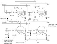
Frank what do you think about this mod for the Futt or the NYAL OTL 3?
The output cap network is not shown so the pic is clear obviously that would go back in at actual build time. The lower grids have their own power supply off of the PT so I would split that at the resistor before the control pot in that supply and then just double every going out from there as you would do say in any push pull amp which had a single supply for the output tubes.
On the upper grids it is shown clear what I believe will work.
The reason for this is that it is so difficult to get matched output tubes these days for the 6FW5's, 6BH5's & the 6LF6's that this should allow for separate adjustments for each unless I am missing something.
Any comments?
Thanks!!
Attachments
If you want a reliable OTL for guitar amp use, consider that it has to deal with overdrive on a continuous basis. The 'totem pole' OTLs might object to that treatment with oscillation that can fry a driver and/or power tube.
That's why, at least for this application, the Circlotron output is preferred. You can run it with zero feedback, so that amp can be quite stable, and if you have several drivers in series, you won't need an output coupling cap, DC Offset control, or even a bias control if you aren't worried about class A operation.
The trick is really the load. with 4 6AS7s and 4 8-ohm drivers in series, or 2 16-ohm drivers in series, you will be easily able to make 50 watts. The plate voltage will have to be around 170V or slightly more, and the the bias about 30ma per section at idle. Under such conditions if a tube arcs the speakers will be perfectly safe.
Some years ago I did a buy of power transformers that will suit nicely for the B+ and filament circuit. Its a torroid and runs slightly warm after hours of operation. If anyone is interested contact me- they are $80.00 each 'till gone. I think I have about 10 or 11 left. You will still need a driver power supply, but only B+.
There are a variety of ways to do the driver. Obviously you want symmetrical drive and you can do that a number of ways quite easily. The thing that has intrigued me recently is this: the amp sounds very good, has the cleanest clean tone in town. I think it could be a bit more aggressive in overdrive- right now it sounds sort of like a Fender with bandwidth, only smoother. I was thinking that an interstage coupling transformer would be fun- driven by a single 6SN7 section. You might be able to build the power amp section with the 4 power tubes and one 6SN7!
The nice thing is that if you do this right, the resulting combo is light, and can keep up with a Fender Twin easily, so long as you are careful about the drivers.
- Status
- This old topic is closed. If you want to reopen this topic, contact a moderator using the "Report Post" button.
- Home
- Amplifiers
- Tubes / Valves
- OTL for dummies.