Hello all...
I recently finished up my first tube project (a Bottlehead S.E.X kit)which turned out better than expected and I would like to move forward with a simplified scratch-built project. I thought I'd give John Broskie's "TCJ Cathode-Coupled Amp" a try.
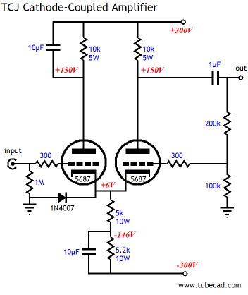
My initial plan is to use Edcor's XPWR104
with a pair of Tung Sol 5687s. Ok so far?
I feel confident that I can safely follow the schematic, but I have a question regarding the heater circuit. JB suggest referencing the heater circuit to +40 V. How do I do this? Does this mean that my heater circuit should be 40V-46.3V (low-hi)
Thanks
7/10
I recently finished up my first tube project (a Bottlehead S.E.X kit)which turned out better than expected and I would like to move forward with a simplified scratch-built project. I thought I'd give John Broskie's "TCJ Cathode-Coupled Amp" a try.
My initial plan is to use Edcor's XPWR104
with a pair of Tung Sol 5687s. Ok so far?
I feel confident that I can safely follow the schematic, but I have a question regarding the heater circuit. JB suggest referencing the heater circuit to +40 V. How do I do this? Does this mean that my heater circuit should be 40V-46.3V (low-hi)
Thanks
7/10
You've got the basic idea. Make a voltage divider between B+ and ground out of two resistors sized so as to draw a milliamp or two and for their junction to have about 40V on it. Bypass the lower one with an appropriate cap to ground (1-100uF).
If you're using DC heaters, attach the (-) end to the junction point at 40V.
You can do something a little trickier which will really suppress common-mode noise and that is to build your heater supply with two regulators, one +3 and one -3. The common point is then the one biased up.
The heaters should be locally bypassed for RF.
- Status
- This old topic is closed. If you want to reopen this topic, contact a moderator using the "Report Post" button.