I have built a couple Tube Preamps (12B4, 5687) exactly as shown on the posted schematics - but find in a couple of occasions, to reduce Hum, I had to raise a few resistor values on the PS filter (RCRC). I did not want to change to an LC type filter (too expensive) or change my tranny (Triad N68X)
In one case I had to raise the RCRC filter resistors from 220R to 2KR before the hum was acceptable... This ends up reducing the B+ voltage and ultimately voltage on the plates by a bit.
But reducing the value of the Plate resistor a bit can raise the Plate voltage to where the schematic requires...
Question is what is most important - keeping true to the B+ voltage or the Plate voltage? My guess is the plate voltage is more important and how you get there is irrelevant... as long as you try to stay above 2x to 4x tube plate resistance on plate resistor (depending on who you talk to)...
Sorry for the lame question....
I have 80V on the plates of a 12B4 pre and the schematic lists 90V...wondering if it is worth changing a few things to get that extra 10V is really worth it...
Hi John,
First, your question is not lame. From experience, and without knowing your circuit, I would say that an extra ten volts on the plate will not change matters very much. Since B+ and plate voltage go hand in hand, you can't really seperate them too much. But at eighty volts you're within ten percent of design value.
If you're experiencing hum problems you may well have other conditions that's causing it. First you must determine if it's sixty or one twenty cycle. (I'll guess 120) Without knowing exactly what you're working with, I can only mention the many usual suspects.
These include: layout, parts placement, orientation, lead dress, filter cap and parts quality, grounding system, (buss, star, multi point) ground location or loops, shielding, etc, etc.
Also, as was mentioned elsewhere on this board, you should have and know how to use an oscilloscope. They are an indispensable tool if you are going to be working with electronics.
Victor
Thank you for your reply...
I would say 120cps hum...If the hum reduces with the higher value resistor on RCRC, wouldn't that be the problem? Major hum with 220R, next to none at 2KR...
I also forgot to say I have AC on the heaters - both leads referenced to ground with 100R each. Thought about DC on the heaters, but someone advised upping the RC filter resistors first...
I have an osciliscope, but don't yet know how to use it (I got it off ebay for $40) Textronics 5110 I think.
Maybe this weekend I will putz around with it...
Ah ha. Next to none reads a lot better then acceptable. Acceptable is a relatively wide term. If it works and sounds good with the higher resistor, then use it that way. But I'm curious about one thing. You say it's an RCRC. Perhaps lower or even loose the first R, unless it's only a very low inrush value. You could also try splitting the 2K with a third C in between. Just a thought.
I'm very familiar with the whole Tek line since I buy and sell equipment for a living. The 5110 is a nice unit for audio. They're no longer supported but there's lots of them around.
Victor
I'm very familiar with the whole Tek line since I buy and sell equipment for a living. The 5110 is a nice unit for audio. They're no longer supported but there's lots of them around.
Victor
As far as "acceptable" and "next to none"
"Acceptable" hum is noticeable on a pair of high efficiency speakers and a gainclone, but "next to none" hum is on my inefficient (84 - 86db/watt) magnepans and a UCD400 setup.
Since the intent was to stay in the UCD/Maggie setup, I am OK with how it sounds..
I have the 220R/270uf/1KR/270uf arrangement as you mentioned not the other way around.
With a 35mA constant current source, this checks out with PSU designer at 230V for B+. I measured 235V B+ and 82V on plates.
Anyway, I so desperately wanted to see this 12B4 best my Foreplay III (with Auricaps mod), but I have to give the nod slightly to the FPIII right now. Sound is just a more dynamic and precise...Of course the FPIII is $400 and the 12B4 getup was about $75 including the enclosure...I have to admit I went on the cheap on components.
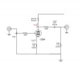
Here is the circuit (Frank's 12B4 I believe - you all have see it before), with only difference is a 2.2uf Bennic Cap, 420R on cathode and 50k Blue Velvet pot...and a B+ of 235V.
"Acceptable" hum is noticeable on a pair of high efficiency speakers and a gainclone, but "next to none" hum is on my inefficient (84 - 86db/watt) magnepans and a UCD400 setup.
Since the intent was to stay in the UCD/Maggie setup, I am OK with how it sounds..
I have the 220R/270uf/1KR/270uf arrangement as you mentioned not the other way around.
With a 35mA constant current source, this checks out with PSU designer at 230V for B+. I measured 235V B+ and 82V on plates.
Anyway, I so desperately wanted to see this 12B4 best my Foreplay III (with Auricaps mod), but I have to give the nod slightly to the FPIII right now. Sound is just a more dynamic and precise...Of course the FPIII is $400 and the 12B4 getup was about $75 including the enclosure...I have to admit I went on the cheap on components.
Here is the circuit (Frank's 12B4 I believe - you all have see it before), with only difference is a 2.2uf Bennic Cap, 420R on cathode and 50k Blue Velvet pot...and a B+ of 235V.
Attachments
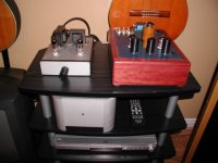
Here is a pic of the FPIII, the 12B4 in a nice anodized Hammond Enclosure (I love these), and the UCD400 in a cool looking (but expensive) Hexateq enclosure.
SY- - the CSS your advising - with an LM317 on the cathode, right? Just dial in a voltage and Viola?
Edit - whoops, I see you posted CSS Plate load....
SY- - the CSS your advising - with an LM317 on the cathode, right? Just dial in a voltage and Viola?
Edit - whoops, I see you posted CSS Plate load....
Attachments
Well SY, if I read John's original post correctly a CCS is not really an option. Sure it would be beneficial but would require still higher B+. And I'm assuming you mean a tube CCS and not one of those nasty little transistor thingies. (sticks tongue in cheek) So a new power trans would be needed. Or else a votage doubler (ugh) which means more parts and more expense plus a redesign. Or is there something I'm forgetting?
Well on second thought you might be able to make it with the available voltage.
Victor
Well on second thought you might be able to make it with the available voltage.
Victor
Victor, the silicon devils may have their deficiencies at audio, but for keeping voltages or currents constant, they are the drug of choice. For a cascode CCS (bipolar or, even better, depletion-mode MOSFET), you only need a few volts to keep them alive. In return, the tube gets to operate in a very happy environment and is empowered to give its best.
Hi,
You can add one or 2 more RC stages while reducing the existing resistors thereby keeping the same B+ value. It is quite effective to increase the number of RC combinations even when keeping the same voltage drop and the same total amount of capacitance, (a 4 section RC combination have an attenuation slope of 24dB/octave while a 2 section have only 12dB/octave.
There is a handy table in Morgan Jones book that give recommended values and figures of attenuation, in that table attenuation for 2 sections is given as 130 times while for 4 sections it is 7520!
I used a 4 section RC filter in my Marantz 7 clone and it was very quiet even on the phono section without any electronic regulation.
Regards Hans
Supply Caps to Big - Slows the Preamp Dynamics?
I have been playing around with the preamp and can deduce that most of the hum can be reduced by better wiring of the inputs/outputs etc. I was in a rush to build and temporarily had it set up intending to correct later...
But another question remains - I have two 270uf 450V caps on the CRCR supply to get my B+ and have read that too big of supply caps slows the music down.
I have noticed on a few power supplies that the power caps are much smaller - including the Marantz 7C - they use a CRCRCRC circuit and none of the caps are over 47uF...is there any truth to the too large of caps is bad - slowing down the dynamics? Better to have more RC circuits than larger caps?
Attachments
read that too big of supply caps slows the music down.
The problem with freedom of speech is that people can say all sorts of nonsense.
Now, that's a different question than the effect of making the first cap in a cap input filter very large (bad! High ripple currents). And a different question than the advantages of using several smaller caps (and associated resistors) instead of one larger cap (good, lower ripple voltages).
There are some advantages to using several smaller caps, but they have nothing to do with ridiculous assertions about "slowing down music."
Well, I changed the Filament from AC to DC and 99% of the hum is gone. Simple as connecting a diode bridge, a .5ohm 5W resistor, and a singe 10,000uf 16V cap. Violla.
Also, I just realized a cool thing about this pre - I built a 9 component Gainclone from old parts laying in my stash (intended to be my test amp so i don't wreck my reference stuff) and I totally forgot the DC blocking caps. I was wondering why I had all sorts of hum and crap from all my SS preamps, even my trusted lightspeed sounded horrible.
Only my Tube pres (Audio Note M7 clone, 12B4, and Foreplay III - all have DC on Filaments) sounded good. Real good. Then I realized the tube pres all had DC blocking caps...
I guess if I need to use the other preamps I will need the caps...
too big of supply caps slows the music down
Not ridiculous at all. If you listen to a lot of rhythmic based music (especially complex polyrhythmic) the subjective difference between a very large and moderately sized capacitor bank can often be quite apparent. Some amp manufacturers who major on PRAT (Naim springs immediately to mind) design their amps accordingly.
IMHO the effect is exacerbated with wideband speakers which exhibit excessive overhang at low frequencies. Large capacitor banks are generally capable of more sustained VLF energy output. Unless you speaker exhibits an excellent low frequency transient response (usually quite expensive to engineer) the outcome can be a subjective slowing or blurring of rhythms. Speakers which are engineered more for realistic transient response than LF extension (the original QUAD ESL is probably a good example) appear to be less prone.
I assure you the effect can be quite real.
Hi John 65b
If I understood it correctly , you have a TWO sections RC filter ,
where the total resistance is 1000 + 220 ohms = 1220 ohms .
As tubetvr had suggested , try to split it in a FOUR sections
RC filter , where the total value of R ( 1220 ohms ) remains
unchanged , you can use for example :
270 uf ( or even less , may be 47uf ) + 390 R + 270 uf + 270 R +
270 uf + 270 R + 270 uf + 270 R + 270 uf .
As tubetvr had mentioned , the Morgan Jones book table says
that the ripple attenuation will increase from 130 times to until
7520 times .
You will be surprised with the good result of this circuit .
Note : I am suggesting to use the 270 uf x 450 V , because you had said that you already have them .
You may even not use the 270 uf x 450 V caps ( expensives )
because any 100 uf x 450 V can do the job .
As an extra bonus , you will get a “soft start” for the plate voltage , without any trace of hum
Regards ,
Carlos
- Status
- This old topic is closed. If you want to reopen this topic, contact a moderator using the "Report Post" button.
- Home
- Amplifiers
- Tubes / Valves
- Question on what is more important B+ or Plate Voltage