Hi, Am currently building a stereo amp largely based on the dynaco ST70. I am just designing the signal ground pathway. I am going with a bus bar ground and my question is this - should I design the ground as if each channel was separate with two separate signal grounded points or should the signal grounds come together just prior to meeting the chassis. As an addition to this question, I was planning to have a separate grounding point for the power supply transformers and caps (probably the safety earth ground point) - does this sound reasonable? I am struggling a bit with the practical aspects of grounding even though I have read a lot of the posts.
Cheers,
Rob
Cheers,
Rob
Your best plan is to provide a safety ground to chassis near where the power cord comes in.
If you choose a star ground system, you can keep two separate grounds floated from the chassis, then bring them together near the input jacks. Return that point to chassis, preferably through a ground breaking resistor or resistor-diode-cap parallel combination.
Make sure the power supply has only one ground return, which you can bring to that common point, and that you don't break into the high ripple loop of the transformer, diodes, and input cap.
Rob,
IF you have separate power supplies for each channel run 2 signal ground bus bars, one for each channel. They should have a common connection to chassis at the amplifier input end. Connect to the bus bars in a connection follows signal way, that is the first connection (closest to the chassis connection) should be the grid 1 resistor of the first tube then the cathode connection, then any anode supply bypass cap etc. Right at the other end of each bus bar will be the main HT filter cap 0V connection. You could call this "connection follows schematic" if you like.
The idea is to keep large circulating return currents like the main filter cap charge currents at the extreme end of the bus bar, away from the chassis connection and the low signal sections.
I have used this scheme whth a common power supply for both channels where I just connected the extreme ends of the two busses at the main filter capacitor (but not to chassis). While that does introduce a physical "earth loop" it did not seem to cause any noise problems.
Else use SY's scheme.
Try to plan your physical layout such that the chassis earth connection for the "start" of the buss bars is opposite side or opposite corner of the chassis as your mains earth "safety ground" chassis connection.
Biggest hint I can give from building about 10 tube amps is do not try to jam it all onto a too small chassis. Give yourself plenty of space to work.
Cheers,
Ian
Hi Ian,
I have a common power supply so I will use your second option. The schematic suggests that the bus bar is connected to the input jack through a 10K resistor , I am not really sure why? I was under the impression that the power supply and caps should be grounded separately but from what I understand from your reply (and from a couple of other replies you have made on this subject, the prower supply ground can be hooked up to the bus bar after the common to the OPT? In principle is it better to use star grounding with a stereo amp?
Thanks for the very useful information.
Rob
Probably 10R, not 10k.
I've used both bus and star schemes in stereo amps and either works just fine if done properly. For the bus system, think of the power supply as one end of the bus, with stages of successively lower current attached along it, and terminating at the lowest current spot of all, the input. Two such streams ending at the same input spot will do wonders to help make your amp quiet and stable.
I've used both bus and star schemes in stereo amps and either works just fine if done properly. For the bus system, think of the power supply as one end of the bus, with stages of successively lower current attached along it, and terminating at the lowest current spot of all, the input. Two such streams ending at the same input spot will do wonders to help make your amp quiet and stable.
Just out of passing curiosity what do you chaps use for your bus bars?
Is a fairly heavy gauge wire (thick enough to be "rigid" under it's own weight) that happens to be lying near the work bench the normal thing you use, or do you buy something more heavy duty such as a 5mm wide strip of copper or copper foil "tape"?
Does an excessively chunky bus pick up EMI?
Is a fairly heavy gauge wire (thick enough to be "rigid" under it's own weight) that happens to be lying near the work bench the normal thing you use, or do you buy something more heavy duty such as a 5mm wide strip of copper or copper foil "tape"?
Does an excessively chunky bus pick up EMI?
I use what we call Romex here in the U.S which is the mains wiring inside the walls of your house. I strip and tin it. It's pretty stiff and has nice low resistance. I use 14 ga (15Amp) size. I should mention it's copper, not alumin(i)um which afaik is impossible to solder to - I've not tried it, but that is my recollection.
Connect the power transformer center tap to the negative side of your first supply cap (usually a good point to tie the first cap in the bias supply too as well) and bring that point to the next set of caps and from there into your ground buss. This keeps the cap charging currents on the input caps contained to a very tight loop, a good way to help keep rectification buzz out of your amplifier outputs.
Connect the power transformer center tap to the negative side of your first supply cap (usually a good point to tie the first cap in the bias supply too as well) and bring that point to the next set of caps and from there into your ground buss. This keeps the cap charging currents on the input caps contained to a very tight loop, a good way to help keep rectification buzz out of your amplifier outputs.
Pete,
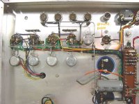
I almost always use number 12 tinned copper buss wire from a large spool I bought years ago. I like it to be self supporting and to remain straight as I connect wires and leads to it. There's nothing more shabby looking then a crooked ground buss. In the attached picture of an amp under construction, the ground point is at the output filter as Kevin suggests and near the input XLR connector. The first input tube is also right nearby.
I've never heard of a proper ground buss picking up EMI or RFI. After all it is at ground isn't it? You'd have to be right next to a 50KW transmitter for that to possibily happen. And even then the wavelength of the buss wire would be way too short for frequencies of that power level.
Victor
Attachments
In reply to Sy
Hi Sy,
Thanks that makes sense. It is 10R, not 10K. My only remaining question is this - should the bus bar be grounded to the chassis directly and the input common attached to the bus bar through the 10R resistor or should the bus bar be terminated on the chassis through the 10R resistor?
Cheers,
Rob
PeteN said:Just out of passing curiosity what do you chaps use for your bus bars?
Does an excessively chunky bus pick up EMI?
No. By using thicker wire one lowers the impedance. I use 4mm copper wire in a matrix grid system. This requires a good quality fat tipped soldering iron. By using such large OD, one can take some liberties but circuit hum is insignifigant and embedded with amp noise. The power caps are starred at one point away from sensitive stages. I don't always rely on the chassis for ground as sometimes in MI stage apps, hum can be a circulating external cable problem and one has to lift off the ground connection. The line earth is always connected to the screen of the power transformer. This protects the user.
When a swithed mode power unit is used, one has to be even more careful as it is a source of potential interference and a really thick earth amp circuit can go a long way to solving RF problems.
richj
Rob, ground the bus right at the input. Now remember, "ground" in this context is signal ground, not safety ground. The inputs should be floated from the chassis.
You can tie the signal ground to the safety (chassis) at the input, but that's where you use the groundbreaker to prevent hum loops.
Pete, what Kevin and Rich said. Thick is good, thick silver is better. I do that same as Kevin for most of my equipment- thick copper liberated from a roll of Romex. My phono preamp uses a thick silver bus, just because I was trying to do everything I could to minimize noise.
- Status
- This old topic is closed. If you want to reopen this topic, contact a moderator using the "Report Post" button.
- Home
- Amplifiers
- Tubes / Valves
- 1 signal ground or two?