I could argue your point of:
If you cap-coupled an AC signal to the grid, then when the signal goes positive, it will draw current from the G-K diode. Where does this current go? Why, clearly, it constitutes a negative bias voltage due to the rectification of the applied signal.
And don't get pissy with me about leakages...we are ignoring those in this scenario.
So where's the DC g-k path, hmm?
Tim
I'll happily repeat again, and I would welcome somebody trying to disprove it, but: ALL THE ELECTRODES IN ANY TUBE MUST HAVE A DC PATH TO THE CATHODE.
If you cap-coupled an AC signal to the grid, then when the signal goes positive, it will draw current from the G-K diode. Where does this current go? Why, clearly, it constitutes a negative bias voltage due to the rectification of the applied signal.
And don't get pissy with me about leakages...we are ignoring those in this scenario.
So where's the DC g-k path, hmm?
Tim
Sch3mat1c said:it will draw current from the G-K diode.
The grid and cathode do not form a diode. The grid is negative with respect to the cathode, so how can any diode be formed?
And don't get pissy with me
Excuse me?
Tim, the statement I made about all electrodes needing a dc path to the cathode can be found in the first few pages of Radiotron. It is stated very clearly. I did not make it up, and I'm pretty sure RCA and Mr Langford-Smith knew what they were talking about.
You're going to have to retract later on, but please continue if you feel it's necessary.
You're going to have to retract later on, but please continue if you feel it's necessary.
Sch3mat1c said:Or are you saying that, in a rectifier, the tube alternately becomes a diode and a - nothing? - every 60Hz?
In fact, that's exactly what it does.
")
Here is some reading online:
http://www.tpub.com/neets/book6/20f.htm
And this describes diodes when presented with an AC voltage:
http://www.tpub.com/neets/book6/20b.htm
cheers
GRID LEAKS.
Hi,
Let me get this straight from the start:I don't want to stirr things up any further but:
Neither have I, however when you use a cathode bias and don't connect anything to the grid you will still notice a negative voltage developping at the grid.
This take time and by adding the gridleak resistor the biasing process is sped up.
As Gabe pointed out the tube will function.
Sure enough it will function as a diode until a load is added to the grid.
While I toyed around with omitting bleeder resistors from the preamp end I noticed an opening up of the sound,with more air and splashier highs on rimshots.
As if a small veil was lifted.
Quite likely there must have been an impedance mismatch somewhere along the line.
Later on I increased the value of the bleeder resistor from 100K to 1M and I came close to the same result as without the bleeder.
Hope this clarifies some,
Hi,
Let me get this straight from the start:I don't want to stirr things up any further but:
And no, this is not "internal" in any tube I've ever seen.
Neither have I, however when you use a cathode bias and don't connect anything to the grid you will still notice a negative voltage developping at the grid.
This take time and by adding the gridleak resistor the biasing process is sped up.
As Gabe pointed out the tube will function.
Sure enough it will function as a diode until a load is added to the grid.
While I toyed around with omitting bleeder resistors from the preamp end I noticed an opening up of the sound,with more air and splashier highs on rimshots.
As if a small veil was lifted.
Quite likely there must have been an impedance mismatch somewhere along the line.
Later on I increased the value of the bleeder resistor from 100K to 1M and I came close to the same result as without the bleeder.
Hope this clarifies some,
Joel wrote... somewhat erroneously:
In a triode biased in class B in a detector circuit, the grid and cathode do indeed form a diode detector, with the grid as the "anode". The same function of grid as "anode" or "plate" is true in a pentagrid converter. The second grid is actually the "plate" of the first "triode" grid.
The definition of a diode, functionally (the key word), is to "rectify", or allow current to flow in one direction but not the other. When the grid is biased negative enough to just cut off the tube, or class "B", then anything that brings the grid toward positive turns on the tube. Anything below that voltage level, does not turn the tube on. So... the grid/cathode circuit becomes a rectifier... a diode. Plate current follows the changes and with a load resistor, "amplifies" them.
Don't they have that in the RDH? It is in the seven or eight books, and countless electronics magazines, I have read about it since I was 10.
As for the path... when the tube conducts, there is a path already made between the cathode and the grid... simply because the grid is in the way of current flow. The grid can impede the flow of current with AC simply because the negative peaks will cause it.
Re the grid as a plate, again to bring up an icon in the business, Steve Bench has made amplifiers where the output is the grid. He says they sound very good.
Cheers!
Gabe
The grid and cathode do not form a diode. The grid is negative with respect to the cathode, so how can any diode be formed?
In a triode biased in class B in a detector circuit, the grid and cathode do indeed form a diode detector, with the grid as the "anode". The same function of grid as "anode" or "plate" is true in a pentagrid converter. The second grid is actually the "plate" of the first "triode" grid.
The definition of a diode, functionally (the key word), is to "rectify", or allow current to flow in one direction but not the other. When the grid is biased negative enough to just cut off the tube, or class "B", then anything that brings the grid toward positive turns on the tube. Anything below that voltage level, does not turn the tube on. So... the grid/cathode circuit becomes a rectifier... a diode. Plate current follows the changes and with a load resistor, "amplifies" them.
Don't they have that in the RDH? It is in the seven or eight books, and countless electronics magazines, I have read about it since I was 10.
As for the path... when the tube conducts, there is a path already made between the cathode and the grid... simply because the grid is in the way of current flow. The grid can impede the flow of current with AC simply because the negative peaks will cause it.
Re the grid as a plate, again to bring up an icon in the business, Steve Bench has made amplifiers where the output is the grid. He says they sound very good.
Cheers!
Gabe
Joel,
Please refer to the example of DeForest's experiments here:
http://www.tpub.com/neets/book6/20e.htm
It shows that the triode he worked with flowed 5 milliamps with nothing connected to the grid, while it flowed 10 milliamps with a positive voltage to the grid, and 2.5 milliamps with the same amount of negative voltage.
But note the non connected one. Grid not connected to anything... tube works. Tube theory from the one who invented the thing!
A pure AC on the grid will make the tube fluctuate. But, as those pages you posted brings out, one would not want the AC to bring the tube into saturation or cut off, so applying a DC bias voltage allows one to have an AC voltage such that plate current will vary within the cut-off/saturation points.
The RDH was likely written to discourage engineers from designing less stable tube circuits. Same with solid state. I have seen many SS circuits where only a resistor from base to B+ was used, the most unstable circuit imaginable, but the circuits work. In all the textbooks I have read for solid state, this practice is strongly discouraged.
I rest my case.
Gabe
Joel said:
Exactly. I think "Doc Bottlehead" (WTF???) is taking a big risk in hoping that all the units you hook this thing up to will have a resistance to ground.
DocB has sold a few thousand of those amp kits, with a very good reputation for reliability. He, along with Paul Joppa and the late John "Buddah" Cammille, have brought some very good products to market. It was DocB and cohorts that reintroduced "Parafeed" output topology and the C4S to the masses - both of which have become well-respected and copied.
The "Barnum" statement posted elsewhere in this thread is just another example of the great unwashed and anonymous opining on the Internet. Take your designs, make them affordable, have people buy them and become faithful customers, then you can make such statements without sounding like an ***.
Gabevee said:But note the non connected one. Grid not connected to anything... tube works. Tube theory from the one who invented the thing!
Gabe, c'mon. A tube merely showing plate circuit current does not qualify as it "working".
A triode amplifies.
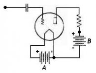
Let's consider the picture below. Where is the discharge path for the capacitor?
Attachments
The "Barnum" statement posted elsewhere in this thread is just another example of the great unwashed and anonymous opining on the Internet.
You're welcome to question my hygiene, but "anonymous" is a lie. A minute spent at my profile and chasing a link of two will demonstrate that I've not done much to hide my identity. What did you think of the mermaid?
(edit: I see that the profile button doesn't exist in the new BB software, but the link to my homepage still does)
Joel,
If I may comment....
The discharge route is through the leakage of the capacitor.
Which is an unreliable factor.
Cheers,
Where is the discharge path for the capacitor?
If I may comment....
The discharge route is through the leakage of the capacitor.
Which is an unreliable factor.
Cheers,
Joel,
As dhaen says the discharge is through the capacitor. When the other side of the cap goes to the opposite polarity, the cap discharges.
Fdegrove,
You are absolutely correct sir. The practice is not good. But the theory is still correct. BTW, 100K grid resistor? Kinda low, IMHO. It does tend to source grid current.
Sy,
While I agree with you, the amplifier that Bottlehead puts out uses a fixed bias (solid state, for that matter) at both the plate and cathode of both the driver tube and the output tube, with DC NFB, so DC bias remains stable. A floating grid will work fine, IMHO.
Gabe
GRIDLEAKS
Hi,
Although it was just an example...the value will depend on the tube used,won't it?
Cheers,
Hi,
BTW, 100K grid resistor? Kinda low, IMHO. It does tend to source grid current.
Although it was just an example...the value will depend on the tube used,won't it?
Cheers,
Joel said:
In fact, that's exactly what it does.
Here is some reading online:
http://www.tpub.com/neets/book6/20f.htm
And this describes diodes when presented with an AC voltage:
http://www.tpub.com/neets/book6/20b.htm
cheers
Hummm none of those links say the diode stops being a diode when it's not forward-biased....

In fact, the first one even says that a triode's grid will act as a diode plate when positive.
So, is the G-K diode real?
Perhaps I should ask you, is a car a car only when it's running? When it's off, is it no longer a car?
Ok back to the topic. I never said it'd be stable nor useful (except in high-impedance circuits, such as an electrostatic sensor), but it will work with no apparent DC grid bias.
Tim
- Status
- This old topic is closed. If you want to reopen this topic, contact a moderator using the "Report Post" button.
- Home
- Amplifiers
- Tubes / Valves
- No grid connection