Hi, all!
Everyone makes its out version of the PSU for the filaments (heaters) - 100 designs for one problem. Let's gather "powers"/experiences...
Let's say we are dealing with ECC88 (6922) - 6.3V and we have 2 tubes, using DC.
What's the "best" way to do it:
- in series (both get the same current)
- in parallel (both get the same voltage, but current is higher - harder to stabilize DC)
- separate (both get... well different - this is why I do not like this, since one channel can play louder due
How to regulate power? CRC? Or the best - battery") Is battery worth trying?
Is battery worth trying?
Thanks,
Matej
Everyone makes its out version of the PSU for the filaments (heaters) - 100 designs for one problem. Let's gather "powers"/experiences...
Let's say we are dealing with ECC88 (6922) - 6.3V and we have 2 tubes, using DC.
What's the "best" way to do it:
- in series (both get the same current)
- in parallel (both get the same voltage, but current is higher - harder to stabilize DC)
- separate (both get... well different - this is why I do not like this, since one channel can play louder due
How to regulate power? CRC? Or the best - battery
Is battery worth trying? Thanks,
Matej
I would say a dedicated regulator for each tube. A 7806 would give 6.0 volts and still be within tolerance. An LM317 could be set for exactly 6.3. Constant current does not have any advantages over constant voltage. Sure it stops turn on surge and extends warm up time but honestly when was the last time anyone experienced a heater failure?
Hi Matej,
Yes, there sure are many designs for DC filament supplys. Some are simple and others needlessly complex. (as in look what I can do) Since everything in electronic design is a choice of compromises, it often comes down to what you have to work with. Meaning space, resourses and goals.
For small signal tubes like you mentioned a regulated DC supply need not be complicated. My personal choice for a pair of 6922s, (let's say at line level) would be solid state rectifiers (either bridge or full wave) to a large electrolytic capacitor (10,000ufd) and then a three terminal 12 volt regulator, with a smaller bypass at the output.
This, of course, would be for a series connection of 12.6 volts. If you wanted the full 12.6 volts (not entirely necessary), insulate and float the three terminal regulator with a single silicone diode between the common and ground.
In most cases a battery supply isn't necessary and often proves to be more if a PITA then it's worth. Unless you're working with extremely low level signals, even then a filter with more sections and/or chokes will usually do the job.
Victor
astouffer said:I would say a dedicated regulator for each tube. A 7806 would give 6.0 volts and still be within tolerance. An LM317 could be set for exactly 6.3. Constant current does not have any advantages over constant voltage. Sure it stops turn on surge and extends warm up time but honestly when was the last time anyone experienced a heater failure?
I used 7805 w/ 2 sillicon diodes connected to the GND pin to get 6.3V.
I got 6.3V for one and 6.2V for the other tube -> one channel plays a little but louder.
Matej
matejS said:
I used 7805 w/ 2 sillicon diodes connected to the GND pin to get 6.3V.
I got 6.3V for one and 6.2V for the other tube -> one channel plays a little but louder.
Matej
There should not be anything close to that sort of difference for only 0.1V difference in heater voltage. Have you moved tubes around between the channels?
Keep in mind that you need at least 3V higher LOWEST input voltage to the 78xx compared to output voltage, for proper operation. Check this out with a scope - a DMM is not good enough, as it shows you the peak (maximum) value of the ripple waveform, you should be looking at the minimum.
Oh yes - regarding heater supply rectification in general, if you need a voltage drop somewhere in circuit, be sure to provide some of it by a dropping resistor BEFORE the filter cap. Remember, you have a low voltage, high current supply, which rectifies into a typically very large filter cap (nx 10000uF is not uncommon). Diode and transformer winding peak currents will be high, reverse recovery will therefore be a problem, and the current waveform will be very ugly - and a transformer works both ways. Some of this bleeds into other windings in the same transformer. Schottky diodes help, but peak currents are still high, so any wires going around there are prone to induction.
ilimzn said:
There should not be anything close to that sort of difference for only 0.1V difference in heater voltage. Have you moved tubes around between the channels?
I investigate a little but more and found out that the problems was on DAC PS.
Keep in mind that you need at least 3V higher LOWEST input voltage to the 78xx compared to output voltage, for proper operation. Check this out with a scope - a DMM is not good enough, as it shows you the peak (maximum) value of the ripple waveform, you should be looking at the minimum.
Now I have 8.5V to 6.3V using 7805. I lowered it intentionally to reduce the heat on IC.
Voltage drop fpr LM7805 is 2V, so I guess this is enough. I tried with 12V SLA and the difference is still there. Maybe there is a difference between 7805 and 7905 or drop on 1N4008.
Oh yes - regarding heater supply rectification in general, if you need a voltage drop somewhere in circuit, be sure to provide some of it by a dropping resistor BEFORE the filter cap. Remember, you have a low voltage, high current supply, which rectifies into a typically very large filter cap (nx 10000uF is not uncommon). Diode and transformer winding peak currents will be high, reverse recovery will therefore be a problem, and the current waveform will be very ugly - and a transformer works both ways. Some of this bleeds into other windings in the same transformer. Schottky diodes help, but peak currents are still high, so any wires going around there are prone to induction.
Thanks for this tip. Currently I am using CRC w/ schottky. I will replace schottkies with SiC diodes ("zero" reverse recovery) to have it more clean.
So in general for the heaters: SLA or CRC + LM317 voltage regulation (should be better to LM7805 due to better ripple rejection, etc).
Thanks,
Matej
Hi,
With thye LM317: how to take care about in rush current with a cold filament at start up please ? I.e, soft start in mind also for the heater.
With a double triode 7803 tube, so 6.3 V/335 mA, I plan after the rectifiers a RCRC, then a LM317 setuped at 6.3 with a pot or two resistors, how would you introduce a suffisant delay to feed the filament without it jumps more than its limit current to expand its span life (at the price of 7803 tubes todays, think it worths it) ?
Could be this one to be good and "slow enough" at starting : 7V Vac, 4 1A diode rectifier (10R - 4700uF -?R -470 uF, or 0,3 H common chocke or 0R1/5W on each rail + 4700 uF + R in the voltage rail only to drope up to the 1,5 needed for the LM317 own drop or a LT1084 (both with trim pot for fine V adjust followed by a 470uF//0,1 uF (wondering if the 0,1 uF is usefull for a heater?) ? I have not simultated yet cause I'm not sure how to handle the soft start effect -far above my basic knowledge-
Well I have a 2* 0-7V/2A torroid, 14 VA should be more than enough I hope !
I plan a simple verroboard...as I'm not aware of simple cheap pcb for that task.
Many thanks for your help.
Last edited:
Start with both filaments in parallel (either AC or DC).
Measure the in-circuit gain of the two triodes.
Is the gain different?
Then that means the rp, mu (u), and transconductance (Gm) are not equal at the quiescent operating conditions.
By the way, if one of those 3 factors is different, at least one of the other factors is different, because . . .
u = Gm x rp
. . . They are all related
The filament voltage is not the only cause of different u, Gm, or rp.
Hi,
thanks,
does it change the heaters voltage needs within the 5% to balance them more than than the already good matching from the factory with this tube ? Not sure I understand the answer... maybe not related to my post above ?
is there a link towards a scheme that has in mind slow start to prevent the life span of a tube heaters ?
Original Post:
"Let's say we are dealing with ECC88 (6922) - 6.3V and we have 2 tubes, using DC."
How well are two ECC88 or two 6922 tubes (4 triodes)?
5%?
Better check them out first, before you believe they are within 5% coming right off the factory floor.
These tubes were originally designed for Cascode RF amplifier service. 5% balance was not needed.
They were not originally made for Stereo Amplifier service, nor for matched balanced operation.
Last edited:
The lm317 datasheet has a simple constant current schematic. But indirectly heated tubes are designed for constant voltage and not constant current. Two tubes limited to the same current may have different gains. Some adjustment may be necessary.
Not strictly correct.
PCC88 for example is specced for current, not voltage.
All to do with it's designed use in TVs
Hi,
With thye LM317: how to take care about in rush current with a cold filament at start up please ? I.e, soft start in mind also for the heater.
With a double triode 7803 tube, so 6.3 V/335 mA, I plan after the rectifiers a RCRC, then a LM317 setuped at 6.3 with a pot or two resistors, how would you introduce a suffisant delay to feed the filament without it jumps more than its limit current to expand its span life (at the price of 7803 tubes todays, think it worths it) ?
Could be this one to be good and "slow enough" at starting : 7V Vac, 4 1A diode rectifier (10R - 4700uF -?R -470 uF, or 0,3 H common chocke or 0R1/5W on each rail + 4700 uF + R in the voltage rail only to drope up to the 1,5 needed for the LM317 own drop or a LT1084 (both with trim pot for fine V adjust followed by a 470uF//0,1 uF (wondering if the 0,1 uF is usefull for a heater?) ? I have not simultated yet cause I'm not sure how to handle the soft start effect -far above my basic knowledge-
Well I have a 2* 0-7V/2A torroid, 14 VA should be more than enough I hope !
I plan a simple verroboard...as I'm not aware of simple cheap pcb for that task.
Many thanks for your help.
Perhaps try the L200 regulator, its got current limit. But high dropout voltage
Perhaps try the L200 regulator, its got current limit. But high dropout voltage
That part is out of production, obsolete. But if one needed both constant current and constant voltage I think any 3 pin Regulator can be assembled in two stages:

You are right about that part being out of production, but there is still stock around. I recently bought 50 from Reichelt. And if the normal suppliers fail one can take a gamble on ebay/Ali
Ive been experimenting with the MIC5156 LDO controller, to do 6.3VAC to 6.3VDC. But that is a different goal. Allthrough that chip can do current limit.
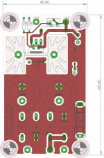
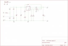
Attached, the gerbers for a board with L200 it has current limit.
Ive been experimenting with the MIC5156 LDO controller, to do 6.3VAC to 6.3VDC. But that is a different goal. Allthrough that chip can do current limit.
Attached, the gerbers for a board with L200 it has current limit.
Attachments
- Home
- Amplifiers
- Tubes / Valves
- Tube filaments (heaters) power supply