time for another round of "Critisize my Circuit"... err..I mean
Have been playing with this circuit in EW8 and CM2K for a couple days now and it appears it may make a good preamp. Just gonna post a few pics, comment if you would like.
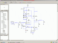
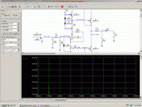
the circuit..
Have been playing with this circuit in EW8 and CM2K for a couple days now and it appears it may make a good preamp. Just gonna post a few pics, comment if you would like.
the circuit..
Attachments
Well, you DID ask...")
Why use a tube with lousy distortion performance?
Why use a quasi-complementary emitter follower? There's much simpler and better performance options.
Is that really a 47uF output coupling cap? I'm unaware of any actual 600R loads out there.
Why use the diode on the tube's grid?
Why bias the tube in such a place as to risk grid current distortion? LED bias is good, but for a line level signals of 1-2V peak, distortion will be much higher than predicted and of a particularly obnoxious distribution of harmonics.
Modeling is fine, but a few minutes on the test bench will be very educational.
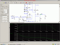
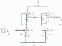
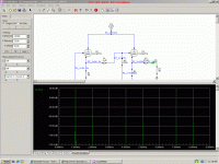
Humor if you will. Consider the circuit in the first post to operate identical to the one posted here. I have replaced V2,3,and4 with transistors. So now we dont have to worry about heater reference for the top tubes. True no amps I know of eaither with a 600 ohm impendance but I used it to give an example of how much it can drive. Even at 5k load the distortion dropped to .003% and entirely 2nd harmonic. And yes true the 12au7 is a lousy tube but its the most accurrate model I have. The diode on the grid is to keep the grid from being pulled to a positive voltage before the tube is warm as is used in many of the circuits over at The Tube Cad Journal. After the tube begins conducting it becomes reversed biased and can be considered out of the circuit. I do wish I had the equipment to do bench testing with but alas all I have is a dmm and an "old" oscope that is suffering from tube failure in the vertical deflection amp. Not sure why the output is quasi complimentary as it is just a current sink loaded emitter follower. The lower transistor doesnt supply any ac current to the load. I am using the led to bias the tube and create a constant voltage source to bias the transistor using the cathode current so that the outputs dont begin conducting until the tube does.
Attachments
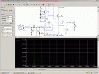
I also am quite aware of that distortion in sims is definitly not real world but rather shows trends, meaning that what reduces distortion in sims will reduce them in reality but by how much etc. will not be correct. Anyway keeping that in mind the fourier for the bjt circuit at 3Vrms into 5k load.
Attachments
The diode on the grid is to keep the grid from being pulled to a positive voltage before the tube is warm as is used in many of the circuits over at The Tube Cad Journal.
There's nothing to pull that grid positive. Note where Broskie uses those diodes (BTW, this is an old scope trick, not original to John)- at the input, all it is is a parasitic capacitance that gets you nothing.
I do wish I had the equipment to do bench testing with but alas all I have is a dmm and an "old" oscope that is suffering from tube failure in the vertical deflection amp.
I don't mean to be rude, but if you want to play with circuit design, you need a scope just as much as someone who wants to work on cars needs socket wrenches. A good second-hand scope is not a very big expense and it is absolutely essential to do anything past assembling kits.
You can put together a very accurate and sophisticated spectrum analyzer for about $100, the price of a sound card and an input buffer.
Once you start playing with actual bits of glass, metal, and vacuum, you'll find very quickly that you can put together something very simple that will outperform most trick circuits.

The point of the Aikido is the symmetry between top and bottom halves. In the SRPP, you take the output from the upper tube's cathode, and the lower tube might have the cathode resistor bypassed (the upper tube is degenerated by the cathode resistor). LED biasing on the bottom is equivalent to a near-perfect bypass. Source impedance is relatively low, rendering a follower stage moot.
In the Aikido, the two halves are degenerated identically and the output is taken from the bottom of the upper tube's cathode resistor, the exact halfway point. The integral follower is then necessary to maintain that symmetry. As part of John's quest for maximum supply rejection, the follower is fed the power supply noise in antiphase to achieve cancellation. All of those features are not present in jerluwo's circuit.
In the Aikido, the two halves are degenerated identically and the output is taken from the bottom of the upper tube's cathode resistor, the exact halfway point. The integral follower is then necessary to maintain that symmetry. As part of John's quest for maximum supply rejection, the follower is fed the power supply noise in antiphase to achieve cancellation. All of those features are not present in jerluwo's circuit.
- Status
- This old topic is closed. If you want to reopen this topic, contact a moderator using the "Report Post" button.
- Home
- Amplifiers
- Tubes / Valves
- Time for another round of "Criticise my Circuit"... err..I mean