It is an High End amplifier?
It have a wide band?
The power is 50w using 2 x 6A3 !!!
http://www.electra-print.com/pushpull_a2.php
Best regards Jaime
It have a wide band?
The power is 50w using 2 x 6A3 !!!
http://www.electra-print.com/pushpull_a2.php
Best regards Jaime
"It is an High End amplifier?"
Doesn't look like it to me. The performance is determined largely by that chip amp up front. These are mediocre performers useful for a quick 'n' dirty solution where fidelity isn't all that important.
Secondly, Class AB2 and cathode bias do not mix. You need a stable source of fixed bias if you're going Class AB2 and you want sound quality above what you'd get from any PA amp.
The 6A3 has a Pd= 15W. You're not gonna get 50W from a pair of those, at least not for very long.
I'd take a pass on this one.
Sorry Jaime,
I have to agree with Miles.
Hey, I saw a couple schematics that didn't use that chip! He must have a drawer full of TDA2030's to use up.
Yeah, skip this and look for something more conventional.
-Chris
I have to agree with Miles.
Hey, I saw a couple schematics that didn't use that chip! He must have a drawer full of TDA2030's to use up.
You really have to be careful with claims like that. Output power is not the most important consideration with a tube amp. This one may put out that power - possibly - maybe. IT would be here for a semi good time, not a long time.The power is 50w using 2 x 6A3 !!!
Errr, depends on the transformers mostly. I am doubtful.It have a wide band?
I have trouble with that too. I'll bet they could sell it as high end in some shops. It has TOOOBS!It is an High End amplifier?
Yeah, skip this and look for something more conventional.
-Chris

There's no way two 6A3 tubes in A2 PP will give you 50W output power.
The maximum efficiency for a class A2 amp is 50% so the theoretical max. power output is 30Watt.
Even running two 300B tubes A2 the power output is restricted to 40W.
If you want 50W from two 6A3's you'll need to run it class B2 requiring fixed bias.
It's a big factor but even worse is the way the grid current is supplied.
The transformer is in series with the 380ohm cathode resistor. For a large part this amp will run class1 (no grid current) so the transformer sees a load of 20k. As it goes into grid current the load changes to 380ohm and due to the grid current a significant portion of the signal is lost in the cathode resistor.
The amplification for class1 and class2 is different, this will give a very nasty distortion at the class1 to class2 transition
No not even close.
Corne
The maximum efficiency for a class A2 amp is 50% so the theoretical max. power output is 30Watt.
Even running two 300B tubes A2 the power output is restricted to 40W.
If you want 50W from two 6A3's you'll need to run it class B2 requiring fixed bias.
Miles Prower wrote:
The performance is determined largely by that chip amp up front.
It's a big factor but even worse is the way the grid current is supplied.
The transformer is in series with the 380ohm cathode resistor. For a large part this amp will run class1 (no grid current) so the transformer sees a load of 20k. As it goes into grid current the load changes to 380ohm and due to the grid current a significant portion of the signal is lost in the cathode resistor.
The amplification for class1 and class2 is different, this will give a very nasty distortion at the class1 to class2 transition
It is an High End amplifier?.
No not even close.
Corne
The maximum efficiency for a class A2 amp is 50% so the theoretical max. power output is 30Watt.
That should be 15Watt not 30Watt.
Corne
found this at Electraprint describing A2 and his use of op-amps -
http://www.electra-print.com/techblog.php?blogid=2
http://www.electra-print.com/techblog.php?blogid=2
I've read the Electra-print article on A2.
This is my opinion:
It has bits of truth, alternative explanations to what is really going on (shifting bias), a solution to a problem (shifting bias) but fail to tell the real solution (don't use a coupling capacitor in A2), compares two completely different things (chips drivers with FB and tube drivers without FB) and leaves out key issues (effective driver impedance at the output tube grid).
In my experience it's possible to design a good tube A2 driver.
Use a high transconductance Cathode Follower (low output impedance) directly coupled (no bias shift) to the output tube grid and a driver with local FB from the CF output.
This will ensure low output impedance and therefore the driver signal doesn't get distorted when the output tube draws grid current. And don't use cathode resistors when using A2.
Corne
Hello,
I built a pair of 6A3 A2 monoblocks last year using the ElectraPrint parts. Took me a few years to get it done. It's a very strong amplifier with good bandwidth and stage. The chip front end was a bit of a bugger to get right. I used a TDA development board from RS as a starter. I don't have the equipment to make serious measurements. A very tiny amount of hum disappears after the units heat up. I also used Jack's matching transformers and a DACT 10K volume control. Very nice.
This is my second amp. The other one being a K-12 modified in the usual ways. Got help from Bruce on the K-12.
Member
Joined 2009
Paid Member
Okay, they spec either a Sov 6A3 or 300B, so this is no 15W Diss 6A3. Never mind that the traditional ratings for that tube are extremely conservative - a lot of modern A3s are built on 300B parts with a different grid pitch. It needs it too at this voltage and current.
I cannot wrap my head around the idea of using a 2030 in any audio application where I care about the sound. This is a part that belongs in the crappy little amps that come in the Guitar Pak at your mass market music store at Christmas time.
ATMO, the only thing they got right in this design is they transformer isolated the TDA from the power tubes so that when it fails and goes full-rail DC on the output the tubes won't be killed and you can use them again to build something decent.
Hello Ronsonic,
One reason the TDA seems to work in this application may be that the B+ rails are low, about 13 volts +-. At low demand the chip has very low distortion, if the data sheet is to be believed.
The tubes are running at the edge. They glow slightly red in the dark. Probably won't get a lot of time out of them. The transformer coupled volume control is said to maintain bandwidth as the volume changes with the DACT 10K. I notice a difference. I may bring the amps to BA this year, but I'm not sure yet. I not a golden ear, but IMHO, people would be surprised at how good it is.
I just bought an OPPO 95 for the CD's. What a difference.
Best Regards, Bill
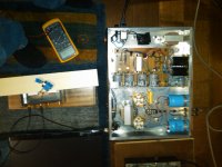
6A3 A2 amp
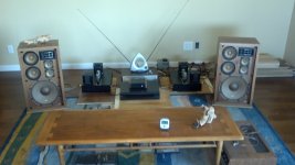
Ok, here are the pictures of my 6A3 A2 amp using the ElectraPrint schematic and iron. I had the bronze plates machined, but I did the rest. The schematic is no longer on the site, but the page will show up if you search. You will also see the transformer volume control I made using ElectraPrint trannys, DACT 10K, and Hammond case - very nice - and a new OPPO 95. I'm running a variac for now. By the way, the speakers are Pionner 88A. I just got the finished cabinets for the Martin King open baffles. See the Quarter-Wave site. I will install the parts myself. Don't have the space or tools to do all of the woodwork.
The amp took quite a while because I needed to learn more than I thought about construction and troubleshooting. I know people have reservations about using a chip front end, but people are welcome to stop by and have a listen. Regards, Bill
Attachments
Member
Joined 2009
Paid Member
Looks good Heybill
Those speakers, they're almost as interesting as the amp - I've never seen or heard speakers that look like that before.
Bigun,
The speakers are the old 4-way Pioneer 88A units I got in 1970 while I was in the service. I sure would like to have a golden ears take a listen to the amplifiers. Maybe the 2012 Burning Amp will be the time.
Regards, Bill
- Status
- This old topic is closed. If you want to reopen this topic, contact a moderator using the "Report Post" button.
- Home
- Amplifiers
- Tubes / Valves
- Hybrid amplifier A2 class