Here is my attempt to design a simple to build SET amp that uses 5842 as the front end, and a 45 to produce a 1 to 2W amp. Hopefully this does not require the use of a preamp. Please provide your thoughts and corrections to any of my assumptions/calculations.
Input Stage
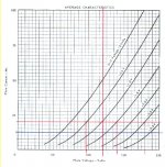
- 5842 with 20mA CCS loading.
- Grid bias set at around -1.5V.
- Grid swing between -0.5V and -2.5V (equals swing of 1V)
- Plate voltage swing with the above settings 95V to 180V. (so a plate supply voltage of say 200V)
- Approximate plate swing of 41V.
- Approximate gain of 40 (rounding down).
- No idea to cathode resistor or capacitor value yet.
Coupling
- 0.22uF with 470K RC coupled.
- f-3dB at 1.5 Hz
Output Stage
- 45 plate load of 5k
- Plate voltage of 250V (from data sheet)
- Grid bias -50V (from data sheet)
- Max plate current 34 mA (from data sheet)
- No idea to cathode resistor or capacitor value yet.
From the above design, I would say that it is a conservative design, that wouldn't drive the 45 into clipping, but should be able to amplify most sources that can output 1V p-p. Schematic is coming (provided this is all good)
This will be used with 90 dB + speakers (most likely 93-96dB).
Thoughts? Suggestions? Comments?
Input Stage
- 5842 with 20mA CCS loading.
- Grid bias set at around -1.5V.
- Grid swing between -0.5V and -2.5V (equals swing of 1V)
- Plate voltage swing with the above settings 95V to 180V. (so a plate supply voltage of say 200V)
- Approximate plate swing of 41V.
- Approximate gain of 40 (rounding down).
- No idea to cathode resistor or capacitor value yet.
Coupling
- 0.22uF with 470K RC coupled.
- f-3dB at 1.5 Hz
Output Stage
- 45 plate load of 5k
- Plate voltage of 250V (from data sheet)
- Grid bias -50V (from data sheet)
- Max plate current 34 mA (from data sheet)
- No idea to cathode resistor or capacitor value yet.
From the above design, I would say that it is a conservative design, that wouldn't drive the 45 into clipping, but should be able to amplify most sources that can output 1V p-p. Schematic is coming (provided this is all good)
This will be used with 90 dB + speakers (most likely 93-96dB).
Thoughts? Suggestions? Comments?
Attachments
Considerable improvement to your design would be the usage of interstage transformer instead of capacitor. It costs more though ...
5842 from Raytheon (NOS) provides exceptional imaging and is considered as a very good choice. Costs about $20 on DIYSupply ... Be aware though that the life of this tube is a bit shorter than of modern tubes ... they say: only 1000 hours. If you are not happy with this, I heard several good sounding 2A3/45 amps using 6SN7/6SL6 in the input stage - that might be also an alternative to 5842.
Good output transformer is crucial.
What about supply ? Tube or SS ? Which one you prefer ?
Regards
Dejan
Hi,
I did something very similar. the only diference is I used 6C45pi instead of 5842, the plate is choke loaded insted of CCS, to ~160Vp, battery bias (1.2~1.4V) on the cathode.
0.47uf PP coupling cap.
310V B+, at i.e. 260V plate, 52V on the cathode, forgo the cathode capacitor of the 45, AC filament.
45 is a wonderful tube on the mid and highs, hope you enjoy it as much as I did.
I drop any cap with any chance I get...
My PS is simple 0.1uf/20H/47uf, dual mono. and regulate the driver's B+.
It's a bit on the heavy side with al the choke... but simple construction.
As for your cathode resistors,
for 5842, you wanted current at 20mA, bias at 1.5V so cathode resistor of this operating point will be 1.5V/20mA=75ohm.
and for 45,
@34ma, -50Vbias, therefore, you need Rc=50/34ma=1470ohm
Hope this help
Cheers
I've used 5842/417A in two of my amps-
1. choke load with 45 - http://azcruz.brinkster.net/diy/AK-450.htm
2. diyAudio CCS load with 10Y/50/300B - http://azcruz.brinkster.net/diy/AK-300.htm
pick your poison. I like them both, and use LED bias (was bypassed cathode resistor) now.
Not having a preamp depends on the source and efficiency of your speakers.
ps.
My 45 amplifier drove an Avant Garde Duo directly from the output of a Clearaudio Balanced Reference phonostage.
It sounds great.
Do you think you'd have enough gain? I'd hardly begrudge 6dB for quiet sources, 6dB headroom for the driver/input stage, and 6 more dB for good measure.
YMMV, naturally, and this amp will probably sound best without another stage. I think I'd use fixed bias in each stage (an LED for the 417) as a way of keeping the gain up. The CCS on the first stage is a good idea. Try 15mA and 150V.
Hi,
From my limited experience, I found that any power amp (2 stage) will have immediate improvement in staging, image defination improve with a pre-amp stage. but some how the "feel" or emotion bit is sort of watered down... I wonder if anyone has the same experience.
Cheers
From my limited experience, I found that any power amp (2 stage) will have immediate improvement in staging, image defination improve with a pre-amp stage. but some how the "feel" or emotion bit is sort of watered down... I wonder if anyone has the same experience.
Cheers
Thanks for the replies. I guess I should describe why I designed this amp. I wanted to put together a simple SE amp that used reasonable common and available parts. Wanted to use an output valve that was readily available NOS and new manufacturer, that wasn't too expensive (always relative). What I wanted also was to bring in a few newer ideas that have been around the mainstream for some years. I wanted to update and modernise the very well documented and built SE amps like the JE Labs SE, etc, etc... I also wanted to keep the costs relatively low and simple construction so that new comers (like myself) can build this amp easily and also learn about tube audio and be able to test and improve this over the years. The amp has to be integrated, so that no preamp was required. There are plenty of schematics and designs that have the 6SN7/6SL7/etc., and I didn't want to duplicate what was already done.
Power Supply
How about a bridge rectification with diodes and a 5U4G that is capacitor loaded, followed by two stages of LC filtering. Using some cheaper Hammond chokes, I think two 7H with 47uF or whatever you have capacitors could work nicely. I have a Elna Cerafine 220+220uF, which will do fine. I was thinking of having a 10uF Solen after the 5U4G, and then one 45uF Solen for each channel before the B+. Something simple and with good performance (at least modelled in PSU2D).
What about using a bleeder resistor to assist in discharging the the caps after power down. What is the best place to put it, and what value/ratings?
Output Stage
Is there a cheap way of implementing a 'parafeed' or parallel feed topology? I was thinking of using James transformers. From what I have read, they are good value.
Coupling
I love the idea of a transformer coupling of direct coupled design. Any suggestions to designs which are cheap (transformer) or safe (direct coupled). Remember this is designed for a beginner.
Input Stage
Will investigate the LED idea, sounds good, and might make the chassis more interesting. So go to find some LED datasheets!
Will get around to a schematic soon...
Thanks!
If your objectives for this project are: simplicity and low-cost, then probably it would be better to use capacitor as interstage. I believe that transformer on this place has to be of a high quality and I am not sure whether you can find them cheap. I really do not know ... I was using Lundahl here and it is definitely not cheap.
Where you can achieve cost reduction is a power supply. Instead of using tube you may use SS diodes and only one CLC filtering stage. Be aware that Elna is also not very cheap (and Elna Cerafine electrolytics are not produced any more) - so probably you will have to search here for a cheaper but good alternative. Maybe something from JJ or Nichicon ... I am using Jensen but they are also quite expencive.
The art of building an amp with these objectives is to find the right measure between used parts, design decisions and compromises that are made and to achive still very good sounding amp. I guess it is possible to do it, but you have to investigate a lot of time in trying and hearing different implemented options. It could be though very interesting journey ..
Regards
Dejan
I designed and built a somewhat similar amplifier recently for headphone use.
The driver stage uses a Raytheon 5842 with a red led and 1N4148 in series for bias of about 2.6V - no cathode bypass caps needed. Loading is via a magnequest 100H (dcr 910 ohms) choke and the plate voltage is 160 -165V depending on the particular tube's transconductance.
The output stage is a fixed bias 71A dht with dc heating. Here you can simply substitute a 45 with either fixed or cathode bias, and you can use ac heating on the 45 without serious hum issues..
I generally prefer fixed bias because it eliminates an expensive cathode bypass cap, but at the expense of a little more supply complexity. Cathode bias of course is safe whereas in the event of a mistake fixed bias missapplied or non-existant will result in a roached output tube.
I used a Russian made surplus teflon coupling cap.
Getting a good choke is less expensive than a good interstage and will give you more linear voltage swing range than a ccs for a given supply voltage. In simulations the choke version was more linear, I did not build the ccs version so I can't compare, but I will say that linearity was very close to the prediction, even at 80Vpp swing the distortion was down better than 60dB, and at saner levels it was close enough to the tester residuals to be unmeasurable.
The 5842 is a very quiet tube as well so the amplifier if carefully layed out with good power supplies should be very quiet. I find elevating the filament supply on the 5842 to about +30V prevents any hum being coupled to the cathode circuit.
My first SE design was a 45 driven by a 6SL7 in srpp, it rewarded me with great sound and finally sold me on SE over PP - to that point I was skeptical to say the least. It is also the only amplifier I've kept from that time frame. The article I wrote about that design is still on my site. It also featured fully tube regulated supplies, somewhat novel for the time.
eeyore said:Output Stage
Is there a cheap way of implementing a 'parafeed' or parallel feed topology? I was thinking of using James transformers. From what I have read, they are good value.
James' are pretty good, but I am not a huge fan of using an air gapped transformer for parafeed duty. You can get some Magnequest parafeed transformers for about $300 (http://www.bottlehead.com/et/MQ/magnequest.htm), or call Electra-Print an he'll wind you some, likely for less money.
eeyore said:Coupling
I love the idea of a transformer coupling of direct coupled design. Any suggestions to designs which are cheap (transformer) or safe (direct coupled).
A good option for direct coupling is DRD or a Monkey topology: http://www.electra-print.com/45drd.php
Actually, this is the prelude amp before I build a 300B DRD. I have been in contact with Jack (Electra-print) on finalising and clarifying some details of his design, and that will be my primary amp once it is built. However, with that amp, I am sparing no cost, Mundorf film caps as the Ultrapath, Electra-print choke load and power supply choke, and either Plitron or Electra Print output transformers. And I will also be mating it with WE300B or Emission Labs 30B.
However, that amp is expected to be very expensive, and I didn't want to start that venture until I have partly designed, understand and completed a point-to-point SET amp with lower voltages (the 300B DRD uses 700+ B+, I was hoping to build one before that, that used below 300V, if possible 240~250V)).
Choke loading for the 5842. Am I to understand that in this instance, the choke acts as a 'CCS', as it allows DC through, but effectively blocks the AC? Also, the response of the choke is frequency dependant right? How would one design/specify the correct choke rating and value? I came across a spreadsheet on VT52 that seemed to suggest that, is that the right way to go?
Input stage: 5842 either CSS or choke loaded, with LED/Diode type bias
Coupling: CR
Output stage: 45 to a 5K load. Cathode bias, rather than fixed bias.
Heaters: Regulated DC or AC with high DC offset on 5842 and AC on 45.
I think that parafeed may be too expensive. Perhaps if the amp can be limited to US$400 without tubes, but with all irons, that might be a good starting point for further design considerations.
Chokes 7H $20 each x2
Output Transformer Pair $145
Power Transformer $50~80
Further thoughts?
hi, I would also suggest you consider using a grid choke on the 45 ")
if I may quote Gordon Rankin on his use of the grid choke on his Cardinal X-1
What the Grid Choke does is this; AC wise this 1500H choke looks like a 188.5Kohm resistor at 20Hz. The DC resistance is just over 3,500 ohms. When the 300B goes into clipping it starts to draw DC current through the grid which re-biases the tube and cuts off the signal Since the DCr of the choke is very low the voltage applied across it is very low making the clipping region much larger which results in a 20% increase in power, without the lose of scale.
Hi,
If your aim is a a good sounding @ low cost + simple, use SS diode inplace of rectifier. CRC for the PS filter, as even the very expensive resistor will still be cheaper then the cheapest choke. & weights like a feather (relatively)too.
Good interstage transformer never come cheap...
Choke is the oldest CCS there is, SS CCS is a replacement of choke for their compact size and weght reduction.
Also, you mentioned that you wish to learn, I strongly recommand to use the simplest topology, i.e. self-bias stages with resistive load for 5842, (this will further simplify your powersupply too) with R-C coupling, OPT at the 45's plate, ... and leave parafeed for the next stage of learning. Leave plenty of room in the chassis for future mods and tweak after you get them singing.
I built my 6c45p+45 last year, started as a simplest CRC ps, R plate loaded, resistor self bias, then to CLC PS, then dual mono, then choke plate, then LED bias, then battary bias, then direct coupling then to 2A3C output stage, which I'm listening to now. Will eventually use this amp as the driver stage for my 845 which I'm still collecting parts for.
You should't leave out PS filter and other caps from your costing. You will have a different balance sheet once you include some decent caps in.
BTW, you will also realise the tube sockets and tubes doesn't constitude a huge part of the amp too. It's always the irons and then the caps...
Cheers
Additional notes,
Build the simplest/basic amp now, enjoy the music first, you need to try very hard to fail any tube amp! Ask anyone here and they will give you the same answer...
Then you decide if you want to further the journey...
BUT please be rational enough to understand that if you can achieve perfect sonic at the first try, this hobby of ours will not have exist in the first place...
Cheers
eeyore said:Actually, this is the prelude amp before I build a 300B DRD. I have been in contact with Jack (Electra-print) on finalising and clarifying some details of his design, and that will be my primary amp once it is built. However, with that amp, I am sparing no cost, Mundorf film caps as the Ultrapath, Electra-print choke load and power supply choke, and either Plitron or Electra Print output transformers. And I will also be mating it with WE300B or Emission Labs 30B.
However, that amp is expected to be very expensive, and I didn't want to start that venture until I have partly designed, understand and completed a point-to-point SET amp with lower voltages (the 300B DRD uses 700+ B+, I was hoping to build one before that, that used below 300V, if possible 240~250V)).
If the amp you are building is really just for practice, I'd forgo the expensive iron and expensive tubes, and just do something simple. Maybe a 12AT7 or 6N1P cap coupled to a 6W6. Use some cheapie coupling caps, some Edcor iron. Parts cost will be well under your budget and it will sound remarkably good.
Here is one I designed for someone else.
But there are tons of variations.
Hi,.
Consider you are planning to aquire or already aquire your tubes and OPT.
IMHO, a 5842 flee power single tube power amp is most benificial.
5842 can pump out ~1w per channel, with your ~90db driver in a proper box, should get 93~96db of listening. and the combo will provide sufficient listening volume of "sound from the pass" beautifully.
How?
PS, Use CRC or RCRC to get 160~180V B+, you can use isolation transformers, AC filament is simple and sufficient.
OPT, ~3K OPt is the normal value, but 5K opt will still get them sing will slightly less power but improve the lineality.
Bias,
start with self bias resistor//bypass cap, or without bypass cap, you can have options of LED in the cathode or even 1.2~1.4V Nicd battery. Fix bias is easily implemented with 1.2~1.4V drycell battery. Pop the OPT at the plate and start listening... Later, you can play with parafeed with choke, or CCS or any concoction you can think off.
I started building ~2year ago, and 5842 was my first SPUD amp, it was real fun.
Cheers
Attachments
It seems that taking the cost of the chokes on the PSU, and using it to load the anode of the 5842 is a better use of funds?
So how would one go about working out the anode choke to the 5842? Can one be had for between US$10 to US$30?
What are the alternative output tubes? I would like to use a reasonably available and cheap directly heated triode. Someone mentioned 6W6, are there others out there?
So how would one go about working out the anode choke to the 5842? Can one be had for between US$10 to US$30?
What are the alternative output tubes? I would like to use a reasonably available and cheap directly heated triode. Someone mentioned 6W6, are there others out there?
Choke loading on the 5842 will depend on what your target LF cutoff point is - my 100H (@ 20mA) chokes measure as -0.7dB around 20Hz, this actually calculates to about 12.5K ohms of xl and with a tube rp of 1.9K this doesn't quite jibe, I am running them at a little over half their current rating and I believe their inductance is significantly higher. (I can't conveniently measure inductances this large.)
Choke loads need some care in construction to minimize stray capacitance, it is not unusual to see the better ones sectioned like output transformers are and Sowter even uses split bobbins on some of their grid chokes. I have a pair of Sowter 4000H chokes and this is what they do - no this is not a typo, yet to try them..
You might find a local winder who can make them for a reasonable price, bear in mind they should be gapped like an SE transformer as well to prevent core saturation from the dc current flowing through them. I could be mistaken, but I believe you will need to budget around $80 - 120 (U.S.) for a pair of suitable audio chokes.
6W6 is neither a dht nor triode, but triode connected is reputedly good sounding. I would recommend the 6CK4 as another viable option, it is a triode and a very linear one at that. (And one I have used extensively.) It's pretty cheap too.
You could sub a resistor for the choke in the power supply at the expense of ripple attenuation and/or efficiency. I don't think using ss rectifiers with 45's is a great idea as imho it is a good idea to delay the B+ until the filament is fully warmed up. A tube rectifier is not all that expensive.
I think though that the end result is worth it. It was a lot of work to get my somewhat similar amp design tweaked, but now I'm very pleased with the sound.
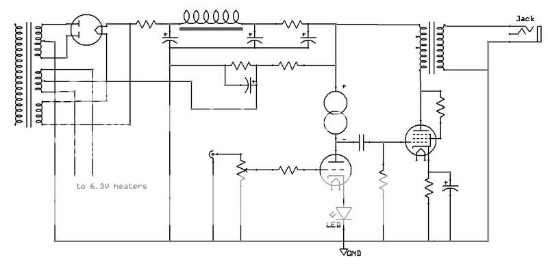
Here is my proposed PSU. The chokes are pretty cheap, and the 5U4G is pretty easily obtainable. The cap values are not too high, and can be easily found. I think that this PSU should be able to be built for aroudn US$100~150.
Note this will serve both channels. Also, I live in Australia so the primary is indicated as 230V/50Hz.
Note this will serve both channels. Also, I live in Australia so the primary is indicated as 230V/50Hz.
Attachments
- Status
- This old topic is closed. If you want to reopen this topic, contact a moderator using the "Report Post" button.
- Home
- Amplifiers
- Tubes / Valves
- Simple 5842-45 SET Amp Design Idea