I haven't seen any applications of this and I'm wondering why . I know it's uneconomical for some tubes that require a lot of negative bias, but it seems like a viable alternative for easy to drive output stages, such as the cheap RH EL84 (or SV83) SE I'm building right now.
An externally hosted image should be here but it was not working when we last tested it.
aletheian said:I have done it. For quick and dirty, I'll either use negative DC voltage for the filaments and use that for bias, or just run a reversed diode from the B+ tranny for a quick and dirty supply and then regulate it.
I have done as above and it works well. I have also used 9V batteries for grid bias with 26 and 01 dhts as well as lithium cells where I needed about 6V for bias.
LEDs can work nicely in the cathode circuit if the voltages add up to the right values as do 1N4148 (can be combined with leds for odd values like 2.6V) I have used nicad batteries in the cathode circuit for pre-amp tubes, but note that the cathode current should be no more than 8 - 10% of the nominal charging rate to avoid overcharging. I have not found NIMH to sound as good, probably due to higher internal source impedance.
High performance ss voltage reference ics in the appropriate voltage range usually have low dynamic impedances and can sometimes be used in cathode bias arrangements with tubes requiring low bias voltages.
Sometimes you can float the negative side of a supply off of a couple of diodes or a zener and relative to the load circuit ground the anode (Zener) or cathode (silicon diode) side of the device will be negative relative to the circuit ground. Three diodes will give you about -2.1V, a zener can be any value you chose allowing for supply overhead - this is a very cheap way to derive both a negative supply and the positive supply from single floating supply. You can also use leds as long as the circuit currents are appropriate - whatever you need to get the drop. This approach incidentally worked out a lot better in a headphone amplifier design that needed -1.3V for bias in a white cathode follower circuit, than the alternative battery circuits I tried. (Hopefully this information is not confusing the issue, and to get what you are looking for I recommend you first model it in spice if there is any question.)
kevinkr said:
...
Sometimes you can float the negative side of a supply off of a couple of diodes or a zener and relative to the load circuit ground the anode (Zener) or cathode (silicon diode) side of the device will be negative relative to the circuit ground. Three diodes will give you about -2.1V, a zener can be any value you chose allowing for supply overhead - this is a very cheap way to derive both a negative supply and the positive supply from single floating supply. You can also use leds as long as the circuit currents are appropriate - whatever you need to get the drop. This approach incidentally worked out a lot better in a headphone amplifier design that needed -1.3V for bias in a white cathode follower circuit, than the alternative battery circuits I tried. (Hopefully this information is not confusing the issue, and to get what you are looking for I recommend you first model it in spice if there is any question.)
Thanks Kevin, .. do you have a circuit on your website that I can use as a reference, if I decide to go this way?
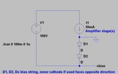
Unfortunately I have not been updating my site much lately and the technique I mentioned in the previous post is not featured in any design on it. However I have included a simple little schematic to illustrate the idea.
Note that the voltage source shown on the left is just your high voltage supply, and it floats. (I.E. No connection to chassis ground at the supply.)
The current source shown is simply the load circuit and can be one or several amplifier stages or an entire amplifier even.
Depending on the bias needed you can use diode strings or a zener, in the case of both it is probably a good idea to bypass them with a small film cap. (Particularly the case with zeners as they are noisy - regular diodes are not, but their internal resistance makes it a reasonable idea as well.)
The currents and voltages shown are quite arbitrary.
One important note is that bias voltages derived this way will NOT track variations in the AC mains, not a problem with my usual regulated supply, but if this is required a resistor can be substituted. To do this you'll need to determine the average operating current in order to calculate the resistor value, and this resistor should be bypassed by a large capacitor so that audio induced current variations do not produce a varying voltage drop across it.
Attachments
zobsky said:
Thanks Kevin, .. do you have a circuit on your website that I can use as a reference, if I decide to go this way?
I've looked at this a bit, as I need to develop a negative bias voltage for the output stage of my hybrid transceiver that piqued my interest in tube audio.
If you can locate a schematic from a 50's Zenith Trans-Oceanic or similar radio that used 3Q4 or 3V4 type outout tubes that require a -4.5 volt bias, it looks like the designers would hold the signal ground above the power supply ground with resistors, and create a potential difference between the two being the bias voltage for the output tube (if I am looking at them right - no guarantee there). A really simple solution.
I've tentatively settled on a 3Q4 ( I have a bunch of them ) for the audio output stage of my hybrid transceiver. I'm planning on making the -4.5 volt bias voltage by sampling the BFO (beat frequency oscillator) output, amplifying it, and then rectifying and filtering it since it will be on the same card with the amp. The military mostly used replaceable button batteries for the bias when they used this tube family.
Interestingly, the prototype amp seems to work fine without any bias voltage ....
- Status
- This old topic is closed. If you want to reopen this topic, contact a moderator using the "Report Post" button.
- Home
- Amplifiers
- Tubes / Valves
- Grid battery biased SE output stages