It'll work, but more often the tube rectifiers and silicon are swapped from shown. Your configuration does have the significant advantage that both the 900V and 450V supplies will be delayed by the tube rectifier warm up time.
Depending on the silicon used you might want to consider a couple of diodes in series with snubbing caps and resistors across them - quieter and more robust in the event of a line transient. (Think distant lightning strikes, etc.) Old ARRL handbooks have a lot of information on HV power supply design you might useful.
Depending on the silicon used you might want to consider a couple of diodes in series with snubbing caps and resistors across them - quieter and more robust in the event of a line transient. (Think distant lightning strikes, etc.) Old ARRL handbooks have a lot of information on HV power supply design you might useful.
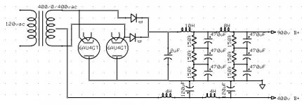
That circuit is CLEVER. The 900 V. rail is bridge rectified, with the 6AU4s forming the negative half of the bridge and the SS diodes forming the positive half of the bridge. The chokes in the filter keep SS diode switching noise out of the rail. The 400 V. rail is FWCT wired in "reverse", which is perfectly "Kosher". Again, the chokes in the filter ensure SS diode noise stays out of the rail. Snubber cicuitry, as Kevin suggested, is needed only if 1 or more filament windings is present on the trafo.
Keep the fact that PSUs are differential, not inherently single ended, in mind. We make them single ended by arbitrarily grounding a point.
Keep the fact that PSUs are differential, not inherently single ended, in mind. We make them single ended by arbitrarily grounding a point.
jayme said:Am I missing something?
Yup.
All four diodes form a full wave bridge, which provides the DC neutral, just as it would if there were no center tap. The center tap and the two 6AU4s form a standard, full wave, rectifier with the polarity reversed, so that the center tap becomes the positive rail with the 6AU4s being in the DC return path. That gives two, positive DC rails with one having approximately twice the voltage of the other. You could also ground the center tap to get a +/- power supply, with a negative and positive rail.
That particular topology has long been used in RF rigs to provide both the high voltage required by the finals, and the lower voltages needed by low level stages and final screen voltage supplies.
Steven,
This circuit can potentially damage the 2x120uF capacitors on the 400V B+.
If the 6AU4s diodes are cold both silicon diodes still form a double phase rectifier with the centre tab as zero.
So after switching on this PSU you'll almost instantaneously have 400V between both B+ leads. The load (imagine a resistor on both 900V to ground and 400V to ground) on both 900V and 400V determines the voltages to ground. If both loads are identical the 900V B+ will be +200V and the 400V B+ will be -200V. This means that the two 120uF capacitors charged in reverse this may cause the capacitors to be damaged.
After warm-up of the 6AU4 diodes the PSU will work as intended.
My suggestion is to replace the silicon diodes by tubes diode and the tube diodes by silicon diodes.
The 400V B+ will switch on instantaneously and the 900V B+ is delayed. If the 400V B+ should be delayed to you should use 4 tube diodes.
Edit :
If there's no load the capacitors on the 900V charge normally but because there's no load the return current must go through the capacitors on the 400V B+ rail. This means the current in these capacitors is reversed. So each time this PSU is switched on the capacitors on the 400V B+ get a reverse current.
This will damage the capacitors.
Corne
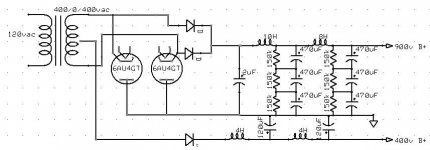
Something I had missed.. This issue can also be resolved with a single clamp diode with the cathode connected to the transformer center tap and the anode connected to ground. The diode will be reverse biased during normal operation and must withstand 400V - 450V so I'd recommend a 1N4007 or similar. During warm up it will be forward biased and will clamp the +400V output to -0.6V which should be safe with electrolytics - note that this issue is not really a problem with film caps at all. (Solens for example.)
With Kevin's solution the 900V B+ jumps first to 450V and then if the 6AU4 diodes are warm it goes to 900V at the same time the 400V will be available.
A delayed start of both voltages can be achieved by placing a diode between the transformer centre tab and the 4Hc hoke (anode to centre tab and cathode to choke) on the 400V B+.
This diode will also prevent the capacitors on the 400V B+ to be negatively charged.
Corne
A delayed start of both voltages can be achieved by placing a diode between the transformer centre tab and the 4Hc hoke (anode to centre tab and cathode to choke) on the 400V B+.
This diode will also prevent the capacitors on the 400V B+ to be negatively charged.
Corne
Attachments
Gentlemen,
Thanks SO much for all of your help. The finished product is shown here:
I am working on getting the chokes wound...Once they arrive then I should be able to breadboard the circuit and report back on a verification that this thing works as needed.
Thanks again,
Steve
Thanks SO much for all of your help. The finished product is shown here:
An externally hosted image should be here but it was not working when we last tested it.
I am working on getting the chokes wound...Once they arrive then I should be able to breadboard the circuit and report back on a verification that this thing works as needed.
Thanks again,
Steve
- Status
- This old topic is closed. If you want to reopen this topic, contact a moderator using the "Report Post" button.
- Home
- Amplifiers
- Tubes / Valves
- Hybrid Rectifier Check Please !