I took the liberty of starting a new thread on this interesting subject. I apologize to Dmitry for cluttering his other thread.
Anyway, this was the last relevant post:
Thoughts?
Anyway, this was the last relevant post:
Joel said:Thanks George. The question at hand though seems to be why my numbers are half those that James got (and presumably Brett since he agreed wholeheartedly).
They calculated a distortion point of 10kHz with a .9mA driver current.
I get a 20kHz point with only .8mA available. And that was a worst-case-scenario of an input capacitance of 80pF.
Can you shed any light on that?
the 71A has Cgk of 3.7pF, Cgp of 7.4pF, mu of 3... 80V swing on the grid.
Thoughts?
Here are the numbers.
Ok, let's use the 2A3 from the other thread.
Cinput=Cgp*(VG+1)+Cgk+Cpk*(VG+1)
So, the input capacitance of a 2A3 is 121.9pF
2piFVp/1,000,000=V/mS
F=20kHz, Vpk-pk=90V
Required slew rate=11.31V/mS
I=C*Sr
.0001219*11.31=1.38mA
So to wrap up, only 1.38mA is required to "drive" the input capacitance of a 2A3. Not very much! And this is at the limit of digital frequency response, and with a FULL amplitude signal input of 90 volts peak-to-peak.
And to finish my example from before, with the 71A, the calculated input capacitance is actually just half what I guessed at. It's really 41.7pF
So.... to drive a 71-A you need only 0.42mA of current.
Joel
Ok, let's use the 2A3 from the other thread.
Cinput=Cgp*(VG+1)+Cgk+Cpk*(VG+1)
So, the input capacitance of a 2A3 is 121.9pF
2piFVp/1,000,000=V/mS
F=20kHz, Vpk-pk=90V
Required slew rate=11.31V/mS
I=C*Sr
.0001219*11.31=1.38mA
So to wrap up, only 1.38mA is required to "drive" the input capacitance of a 2A3. Not very much!
And this is at the limit of digital frequency response, and with a FULL amplitude signal input of 90 volts peak-to-peak.And to finish my example from before, with the 71A, the calculated input capacitance is actually just half what I guessed at. It's really 41.7pF
So.... to drive a 71-A you need only 0.42mA of current.
Joel
Slew rates, op-amps, and glass
At the risk of muddying the waters, slew rate specifications are great for op-amps, but not quite so useful for valves. Try this approach, and I think you will see what I mean...
Find the input capacitance of the load. Determine its reactance at the highest frequency of interest. Use Ohm's law to calculate the peak current at that frequency. Now, go back to the original loadline of the driver stage, and plot that peak current directly above and below the operating point (the phase lag of the capacitance causes it to draw maximum current at zero voltage swing). Plot the maximum voltage swing (positive and negative) on the loadline. Finally, draw an ellipse through all four points. This is your AC loadline.
When I have done this, I invariably feel that I would like a lot more current through my driver to keep the distortion down (even if it is ultrasonic).
...Slew rate current...
First a confession - some of my quoted numbers were wrong due to my sloppy use of Jim de Korts spreadsheet - Sorry .
.
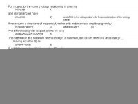
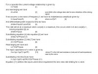
To check I'm doing it right I have derived the equation for input current required for zero slew rate limiting into a valve and my work is included below for all to mock
I will rework my figures and ajust my conclusions as required. My apologises for the confusion that my erroneous figures caused.
ciao
James
First a confession - some of my quoted numbers were wrong due to my sloppy use of Jim de Korts spreadsheet - Sorry
.To check I'm doing it right I have derived the equation for input current required for zero slew rate limiting into a valve and my work is included below for all to mock
I will rework my figures and ajust my conclusions as required. My apologises for the confusion that my erroneous figures caused.
ciao
James
Attachments
James, your derivation from first principles up to Eq. 9 is spot on, and (even more pleasingly) agrees with Ohm's law and the capacitor's reactance at a given frequency.
However, Eq. 10 is rather awkward. Using gmRl is handy for pentodes, but somewhat clumsy for triodes (which, after all, are the ones that have the serious Miller problem). I feel that the following is handier:
Cin = Cgk+Cag(1+A): where A is the voltage amplification to the anode
However, Eq. 10 is rather awkward. Using gmRl is handy for pentodes, but somewhat clumsy for triodes (which, after all, are the ones that have the serious Miller problem). I feel that the following is handier:
Cin = Cgk+Cag(1+A): where A is the voltage amplification to the anode
...the art of assumptions...
Tim,
I given two differnt ones for Miller cap today myself. The first where no reference to a specific circuit applies uses mu as the amplification. The second uses the formal derived expression where gm*R' represents the amplification. The third uses A for the amplification...
Three expressions - one meaning...but then you knew that....
All sing chorus "The games people play..."
ciao
James
Uh... ok, james, isn't that what I just said?
Anyway, no, my input calculation is actually correct. In your's you neglect the stray capacitance and Miller effect between cathode and plate. They exist in the 'real world'.
Please see the R.D.H. - which is where it is taken directly from.
Regardless, when looking at the actual numbers, I think it's pretty clear that the mantra 'you can't overdesign the driver' is silly.
Brett, you were right. It is very basic engineering.
Re: Slew rates, op-amps, and glass
So, are you saying that the necessary slew rate of a 2A3 at 20,000Hz is not 11.3V/mS?
Because if you accept that, then we know exactly how much current is needed. No more, no less.
EC8010 said:...When I have done this, I invariably feel that I would like a lot more current through my driver to keep the distortion down (even if it is ultrasonic).
So, are you saying that the necessary slew rate of a 2A3 at 20,000Hz is not 11.3V/mS?
Because if you accept that, then we know exactly how much current is needed. No more, no less.
Re: ...the art of assumptions...
I do not think that this is true; A seldom equals mu - certainly not in triodes - this depends entirely on the chosen operating point, which also determines gm and therefore ra.
7N7
James D. said:Tim,
I given two differnt ones for Miller cap today myself. The first where no reference to a specific circuit applies uses mu as the amplification. The second uses the formal derived expression where gm*R' represents the amplification. The third uses A for the amplification...
Three expressions - one meaning...but then you knew that....
I do not think that this is true; A seldom equals mu - certainly not in triodes - this depends entirely on the chosen operating point, which also determines gm and therefore ra.
7N7
Joel said:A= voltage gain
So, actually in reality the current requirements would even be a fraction lower than calculated.
Absolutely, since it is A that is used in the miller calculation not mu
7N7
Joel,
what I'm saying is that I don't feel that expressing slew rate in volts per microsecond (s for second, S for Siemen) is particularly useful in a valve circuit. As my earler post describes, we can calculate exactly how much current is required to drive the input capacitance of the output valve. My key point is that it is well worth plotting this on the loadline of the preceding valve because the ellipse may take the valve too close to cut-off for linearity, and that may cause you to choose a higher quiescent current.
what I'm saying is that I don't feel that expressing slew rate in volts per microsecond (s for second, S for Siemen) is particularly useful in a valve circuit. As my earler post describes, we can calculate exactly how much current is required to drive the input capacitance of the output valve. My key point is that it is well worth plotting this on the loadline of the preceding valve because the ellipse may take the valve too close to cut-off for linearity, and that may cause you to choose a higher quiescent current.
EC, If you're saying hey, throw in a .5mA extra to compensate for discrepancies - that's cool with me. My "rant" I guess was that certain respected "gurus" make wild proclamations about the necessary grid current demands for such tubes as 300-B's and 2A3's. They also make statements like "5 to 10 times the calculated value is a good rule of thumb". This is illogical, since the calculated value is already in itself an extreme worst-case-scenario!
I also have had to listen to people critque mine and other people's designs based on these "rules of thumb" - people who have no idea what these numbers mean, or how they were derived.
I also have had to listen to people critque mine and other people's designs based on these "rules of thumb" - people who have no idea what these numbers mean, or how they were derived.
Joel,
I'm saying that you may decide that you want a lot more current. Bear in mind that when you move vertically on a triodes's anode characteristics, the valve really isn't very linear at all - especially near cut-off. I really suggest that you do the sums for an amplifier (perhaps your own), plot the currents, and draw the elliptical loadline. The first time I did it, it gave me a very nasty surprise, and I increased my quiescent current considerably in order to restore linearity.
I'm saying that you may decide that you want a lot more current. Bear in mind that when you move vertically on a triodes's anode characteristics, the valve really isn't very linear at all - especially near cut-off. I really suggest that you do the sums for an amplifier (perhaps your own), plot the currents, and draw the elliptical loadline. The first time I did it, it gave me a very nasty surprise, and I increased my quiescent current considerably in order to restore linearity.
mebbe I have to say something already known-but rule of thumb from ol' good books is-driver stage must have at least 1/10 dissipation of driven stage .
say-we need driver for VT4C with 85 W diss;
for that sort of beast,we need at least 8.5W burned in driver.
believe me-good rule of thumb.
say-we need driver for VT4C with 85 W diss;
for that sort of beast,we need at least 8.5W burned in driver.
believe me-good rule of thumb.

- Status
- This old topic is closed. If you want to reopen this topic, contact a moderator using the "Report Post" button.
- Home
- Amplifiers
- Tubes / Valves
- Slew Rate Limiting... continued.