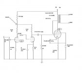
OK...here is the latest & hopefully last design of my 813 SE....I'm hoping some of you out there have some CAD programs that can crunch some numbers for me as I have changed the OPT Z value to match available OPTs. ...The Triode strapped 813 curves seem to elude me...just hoping we are not straying into danger zones as this puppy is a far cry from our folks ol' RCA 'stereophonic' that I was weaned on.....the voltage splitter for my 6SN7s' also is unknown...is it a straightforward voltage splitter or what?
__________________________________Rick.......
If all is cool I'll start gathering a bunch of parts & proto them...I'm also gonna make a chassis out of a local common wood down here called Quebracho...look it up!
__________________________________Rick.......
If all is cool I'll start gathering a bunch of parts & proto them...I'm also gonna make a chassis out of a local common wood down here called Quebracho...look it up!
Attachments
Looks interesting. The only thing that strikes me right off the bat is that I wouldn't use a series dropping resistor off the 900v to supply the 6SN7. Unless you can ensure that the filaments are warmed up before turning on the B+ the voltage (so the 6SN7 will draw current as soon as the B+ gets turned on) the voltage could soar well above the maximum rating of the 6SN7 (450 volts if it's a GTA or GTB, less if it's a plain vanilla version).
I'd use either a separate 400 - 450 volt supply or use a voltage divider with large wirewound resistors instead of the series dropping resistor. This is just off the top of my head, but they'd probably be something like 2- 12K 20 watt or 25 watt resistors. This would ensure that the plate supply to the 6SN7 could never go above 450 volts. You also need a bypass cap at the divider output (maybe 100uf 450v). You could tweak the divider a bit to get a slightly different voltage, but remember that the current drain from the 6SN7 will load down the divider and lower the voltage a bit. A few calculations are in order with the estimated current drain.
Good luck, have fun and be careful. 900v is pretty scary stuff.
Mr. Ellis,
May I suggest that you check out this thread:
http://www.diyaudio.com/forums/showthread.php?s=&threadid=104544
I believe that you may find it helpful.
Regards,
Steve
May I suggest that you check out this thread:
http://www.diyaudio.com/forums/showthread.php?s=&threadid=104544
I believe that you may find it helpful.
Regards,
Steve
813 Triode Curves
I have triode curves for 813.
I cannot send them at present as I am abroad, but email me (VAR1016@gmail.com) in a couple of weeks and I will send them to you.
My first DIY effort was a push-pull 813 amplifier; it underwent many variations, most of which I can rememebr (I think).
The first thing is to be aware that a large transmitting beam tetrode, triode strapped has a large anode to grid capacitance that must be driven (coupled especially with the low value of grid leak recommended by RCA).
My advice? Use a cathode follower. I didn't but I wish I had...
Paul
hey-Hey!!!,
You could try a pentode instead of the cascaded 6SN7's. Rig its plate supply from the U-L tap. With a small TV sweep, you'll get plenty of gain with a medium-sized plate resistor. A shunt-regulator for the input tube's g2 will make short work of that....")
The small TV sweep will have a good plate voltage tolerance, and characteristics to allow it to work from a low g2 voltage. They're cheep too, 6BQ6, 6AV5, 6AU5 to name a few.
Pete Millet did one like this with KT88's and D3a's.
cheers,
Douglas
You could try a pentode instead of the cascaded 6SN7's. Rig its plate supply from the U-L tap. With a small TV sweep, you'll get plenty of gain with a medium-sized plate resistor. A shunt-regulator for the input tube's g2 will make short work of that....
The small TV sweep will have a good plate voltage tolerance, and characteristics to allow it to work from a low g2 voltage. They're cheep too, 6BQ6, 6AV5, 6AU5 to name a few.
Pete Millet did one like this with KT88's and D3a's.
cheers,
Douglas
Bandersnatch:
I cannot see how a pentode with its high output resistance (rout = RL roughly) could drive the capacitance of an 813. This is quite apart from the odd-order harmonics he will probably generate if he swings the volts he needs for 813.
I think that he is right to use 6SN7 (if he has enough gain) and then either a cathode follower or at least a decent low Ra triode driver (or triode-strapped pentode).
Depending on required sensitivity I would try a 6072 (for stereo SE) followed by (if he doesn't want cathode followers) say a 6N30 or perhaps a Tung-SOl 5687 (but this has to run plenty of current).
Paul
Hey Paul,
First off, the input capacitance is only going to be 40%( or g2 % ) of the triode strapped and Miller enhanced. The g2 is only running that percentage of the plate swing.
Second, he's running the power stage open loop, and I suspect that the output Z of that stage is about equal to his load. Some carefully applied NFB would probably be useful.
Since he'd be able to get away with an 8-10k plate load, and with a properly set g2 voltage, I doubt he'll introduce any large qty of anything but 2-HD.
Third, examine the E-Linear amp project from Pete Millett. He builds them SE, and I came upon that same circuit for PP use. The amp got written up in April '05.
E-linear amplifier
I have this amp set up running PP 4E27's driven by 6H6P/FQP1N60 cascode as a LTP phase inverter( triodes on the bottom, MOSFET's on top; the faux pentode ). The filament supplies are capable of lighting 813's with a jumper change and twist of the control variac in the PS. Best amp so far; it has seriously reduced my amp building energy.
Best Regards,
Douglas
Thanks Douglas, Some interesting points.
It is true that the Miller capacitance of 813 will be low since mu is only 4.5 or thereabouts, but the input capacitance will be high, and the driver will have to provide some current to swing the necessary volts I think. About 180v pk-pk I suppose without safety margin.
My reference to odd order harmonics concerned the pentode driver rather than the output stage - especially as it has a high output resistance and pentodes do make odd order harmonics naturally.
NFB would help, but this approach is normally eschewed by SE enthusiasts!!
All the best
Paul
hey-Hey!!!,
Triodes are not above making odd order HD either. PP amps have the additional issue with summing it.
I am not going to run my UL 813's at anywhere near a kV. ~600 will be about it actually. I'll be able to run decent idle current and stay away from the cut-off portion of the curves too.
I have also found a distinct difference between a front-to-back loop of FB and a single plate-to-grid loop in both performance and sonics. I like the short path stuff much better... What I find truly objectionable is an amp that's not able to deal with a speaker's impedance loopy-ness.
cheers,
Douglas
Triodes are not above making odd order HD either. PP amps have the additional issue with summing it.
I am not going to run my UL 813's at anywhere near a kV. ~600 will be about it actually. I'll be able to run decent idle current and stay away from the cut-off portion of the curves too.
I have also found a distinct difference between a front-to-back loop of FB and a single plate-to-grid loop in both performance and sonics. I like the short path stuff much better...
What I find truly objectionable is an amp that's not able to deal with a speaker's impedance loopy-ness. cheers,
Douglas
Well, there have been those like Pete Millet that show that not all pentodes create high order distortion. Take a look at his 813 amp and he uses the 12HG7/12GN7 in pentode mode and shows that the distortion is actually mostly all H2. So there seems to be exceptions to this rule (there are others I've seen too).
hey-Hey!!!,
Don't hold off for a 1kV 813 amp. It just isn't needed. That valve doesn't need its plate at full operating temperature to function as its getter. Run them conservatively, manage the filament voltage carefully and step up the B+ as you're comfortable with it.
Try a full voltage plate TX with a tapped autoformer in its primary to lower its output voltage. Feed it 70-80VAC instead of 120. There are some wound with taps every 5V, so 120 across the whole thing, and taps in 5V increments down from there...
cheers,
Douglas
That is a good idea. I also have some 500VA isolation transformers (huge EI ones) that have multitapped primaries and secondaries that you can adjust voltage with. I could put those in front of the pwr tx.
I bought the 813's as I wanted to try some big bottles and they are cheaper for good old stock than 845's and 211's.
I bought the 813's as I wanted to try some big bottles and they are cheaper for good old stock than 845's and 211's.
Bandersnatch & JoshK,
Again interesting points - obviously these pentodes are special. However it is also said that pentodes are noisy (see Jones - Valve amplifiers 3rd ed.) owing to partition noise.
813 at 600V? quite low power I would guess; at 1kV you should be nowhere near cut-off if you run 90mA - I know that the PSU is expensive - I have been there!
And JoshK I agree the 813 is a splendid valve and will offer great results.
Good luck!
Paul
Edit: Indeed I did run 813 at almost 1.2kV, but later decided that 900V at 90-100mA would give better results. On the subject of feedback I had an output transformer with four equal secondaries, so I connected it for 4 ohms and connected the centre point to the cathodes of the 813s and enjoyed a distinct improvement in the mid-range (I cannot do feedback maths!).
On the subject of high voltages it was once said that to the steeplejack, above a certain point, all risks are equal. That may be so, but even 600V is a high voltage, take great care. I blew up carelessly constructed diode bridges due to tracking. These days I am a little more cautious.
hey-Hey!!!,
Cut off is also dependant on the load. With a 600V/150 mA idle piont, a low a-a load will allow cut-off and be an AB1( assuming no grid drive ) amp. Supporting that same idle point with a proper load is needed to achieve the Class A operation.
I would suggest adopting the automotive definition of high voltage----anything over 50V. Low impedance suplies that work so well for audio amps are not to be trifled with, or taken lightly.
cheers,
Douglas
what is your OPT primary impedance using these operating points, 600v!150mA?
low plate voltages allows higher mu, the 813 has higher mu than an 845, yes?
Obviously it varies with operating point but the mu of a triode-strapped 813 is about 8, thus much higher than that of 845. Gm is higher and thus Ra is lower.
Years ago when I ran my amplifier it operated from memory at about 870V and 90mA per valve. Bias requirements depended on the brand of the valves; the variation was surprising: in general RCAs needed about -75V - -80V at my operating point. I recall an EEV example that needed -115V - perhaps it was gassy! All from memory I am afraid - from about 15 years ago
7N7
- Status
- This old topic is closed. If you want to reopen this topic, contact a moderator using the "Report Post" button.
- Home
- Amplifiers
- Tubes / Valves
- 813 final design?