I'm going to build this as a first tube project:
http://www.tubecad.com/2006/06/blog0067.htm
See the BUF634 section.
So far, I haven't come across anyone who has built this schematic yet.
Question is, do I just build the entire amp as per:
http://www.tubecad.com/2006/04/blog0059.htm
And then add the buffer section?
Or can I ignore the orginal 6GM8 pre amp schematic altogether? It seems like a lot of capacitors, etc, will be missing if it's built as per the schematic with the buffer.
Cheers for any tips.
Attachments
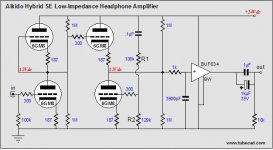
Well, the output caps from the standard Aikido have been moved behind the buffer stage, other than that I do not see a major difference. The "standard" schematics has caps from the tube's internal shielding to ground , they were omitted in the buffered version, I believe, to simplify the diagram and show the fundamental circuit. So build the buffered version and consider including the caps for the shielding.
R1 on buffer schematic = R7 on the original 6GM8 preamp schematic
No, look again! And better still, read thru the wole set of articles and try to understand in more detail how the Aikido works.
- Status
- This old topic is closed. If you want to reopen this topic, contact a moderator using the "Report Post" button.
- Home
- Amplifiers
- Tubes / Valves
- 24V Aikido --> 6GM8 with Buffer