I recently obtained (for no good reason other than the price was right and they looked cool) a couple of interstage type transformers. The person I got them from indicated they were 2.5K:10K with the primary center tapped but not the secondary. My guess is that they can't handle any DC, they are very small. I am wondering if I might be able to use them as input phase splitters in an EL84 PP amp.
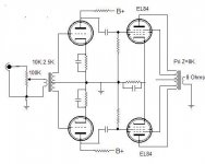
My idea is to 'turn them around' and use the secondary as the primary connecting one leg to a volume pot and the other leg to ground, then connect the primary (now used as the secondary) to the grids of a driver stage, grounding the center tap and driving the EL84s directly from the drivers. The driver tubes could be 6N1P's or 6922's since I have several of each on the shelf. (I think I have some 12AX7's also.)
The attached schematic gives the basic idea. Any feedback would be appreciated.
Attachments
In (simple) theory, you can do this. In practice, the transformer will object to being driven from the high (and variable) output resistance of your volume control, and show this by an HF response that changes with volume setting. Reducing the volume control to 10k might help, but will load your sources more heavily.
The only real way of knowing would be to try it and measure it to death.
The only real way of knowing would be to try it and measure it to death.
I think I'd try using the 6922 in front of the transformer, as an SRPP stage. Cap-coupled to the transformer.
Or, add a low-gain stage in front. I've used 12B4's like this and they do well. Or a cathode follower if you don't need any gain.
I'd bet you'll get really bad (and variable with volume control position) frequency response if you try driving the transformer directly from the volume control.
Pete
Or, add a low-gain stage in front. I've used 12B4's like this and they do well. Or a cathode follower if you don't need any gain.
I'd bet you'll get really bad (and variable with volume control position) frequency response if you try driving the transformer directly from the volume control.
Pete
Johann and Pete,
Thanks for the replies! This is one of those projects that just sort of happened since I had the parts and I want to gain a little experience with phase splitters.
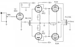
Since wiser, more experienced heads than mine are of the opinion it won't work acceptably as drawn and since a cathode follower would be an easy addition, requiring only 1 more tube for a stereo amp I will probably go that route.
Here's an updated schematic. I'm leaning toward a B1+ of 325V (for the output stage) and a B2+ of 250V (for the cathode follower and drivers).
Thanks for the replies! This is one of those projects that just sort of happened since I had the parts and I want to gain a little experience with phase splitters.
Since wiser, more experienced heads than mine are of the opinion it won't work acceptably as drawn and since a cathode follower would be an easy addition, requiring only 1 more tube for a stereo amp I will probably go that route.
Here's an updated schematic. I'm leaning toward a B1+ of 325V (for the output stage) and a B2+ of 250V (for the cathode follower and drivers).
Attachments
I wouldn't bother with the cathode follower - its not needed to get the best out of the transformer. An anode follower will be simpler and will allow you to compensate for the step down of the transformer.
Because you are stepping down the transformer will behave massively better than normal with a much wider bandwidth,
I would consider the possibility of eliminating the 6922's as drivers by using a front end valve with higher gain in a Mu follower.
Shoog
Because you are stepping down the transformer will behave massively better than normal with a much wider bandwidth,
I would consider the possibility of eliminating the 6922's as drivers by using a front end valve with higher gain in a Mu follower.
Shoog
Shoog said:... An anode follower will be simpler and will allow you to compensate for the step down of the transformer.
... consider the possibility of eliminating the 6922's as drivers by using a front end valve with higher gain in a Mu follower.
Shoog
Shoog,
I hadn't considered that the performance of the transformer might increase with the step down. That's good news.
I have some questions on this approach if you don't mind.
1- Where to put this stage?
A- before the transformer
B- afer the transformer and before the driver stage
C- after the transformer and eliminate the driver stage
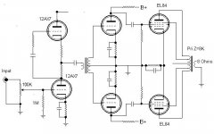
2- I'm a noob when it comes to anything beyond grounded cathode, cathode follower or white cathode follower. In poking around I'm seeing plate followers (using a single triode and giving a gain of maybe 22dB with a 12AX7 and mU followers using two triodes (and to me they look like SRPP stages?) with gains of maybe 36dB with a 12AX7. I'm assuming you mean the higher gain stage?
Here's a shot at it and thanks for the input!
Attachments
The plan you have shown looks workable.
Two small issues, in a Mu stage you don't have the cathode resistor above the take off point on the upper triode. The Mu stage gives gain and most of the drive characturistics of a cathode follower.
Also the way you have it drawn the top triode has no grid reference and so will not work.
A good analysis of the Mu stage can be found at;
http://www7.taosnet.com/f10/mustage.html
What is the voltage ratio you will be getting with this transformer ?
You need this to work out if your Mu stage can give enough gain to drive the EL84's directly. If it is possible to achieve this then you save a valve, and also you have superior drive to the grids of the EL84's which will allow it to better transition into AB2 class.
Shoog
i have been toying with a very similar idea myself using ECL82's and 807's.
However you plan as drawn has one very serious design flaw and that is its poor damping factor. It is very difficult to introduce global feedback into a design with an interstage transformer due to stability issues.
There is a clever fix to get round this. If you keep the 6922 driver stage you can introduce plate to plate feedback ala RH84.
Another subtle refinement is to turn the 6922 into a LTP with a common CCS in the tails.
Also if you do go with the Mu stage, consider the alternative of a CCS loaded anode follower. This potentially should outperform the Mu stage by a long margin.
All in all that would make an excellent little performer.
Shoog
Shoog said:I wouldn't bother with the cathode follower - its not needed to get the best out of the transformer. An anode follower will be simpler and will allow you to compensate for the step down of the transformer.
Because you are stepping down the transformer will behave massively better than normal with a much wider bandwidth
Shoog,
Again a kind of what-am-I-missing reaction. The secondary of the transformer is not loaded, thus, as a first approximation, it can be assumed to be simply an inductor. I do not quite follow why a step-down will be massively better than normal, unless you are talking about Miller-C of the following stage.
Also we do not know the inductance, but Sherman did mention that the component was quite small. Hence it is difficult for me to assume that the inductance would not simply be the governing load in the case of an anode follower. In this respect the response low down would suffer, and also the h.f. response since the equivalent circuit (if we do bring in Miller-C) will be more sensitive to such C as when the primary is damped by a low impedance feed.
You correctly mention poor damping factor in a subsequent post, where you do bring us back to the advantage of a low impedance feed. So? (My alternative: A dual triode, even triode-pentode, with a/the triode direct coupled as the follower?)
Gain factor obviously there, as well as the possible advantages of a tube phase inverter, but I treated the matter as per the original question: How to use an interstage transformer per se (whether or not it is the best way, even to the point of hum induction etc.).
Regards.
This has gotten interesting. I've decided to try the following-
1- First I'm going to hook it up directly to the pot as in input trafo and follow it with a 12AX7, one triode for each output. If it isn't happy with the direct connection to the pot then...
2- I'll buffer it with a cathode follower since I have one already constructed as a buffer for a chipamp. It is a 6922 which is a dandy CF.
volume pot ---> CF ---> trafo ---> driver
Driver stage in this scenario would likely als be a 6922. If that scenario doesn't work out either then...
3- Try a mu follower.
The order of things decided only by the ease with which I can do them.
I'll try to accomplish #1 over the weekend. I've already wired the output stage and I have a couple of bench supplies so I won't have to tackle the PS until I decide on the final circuit. I'll report back with results.
I do not quite follow why a step-down will be massively better than normal, unless you are talking about Miller-C of the following stage.
You have hit the nail right on the head. There will be interwinding capacitance compounded by miller capacitance. A step up makes this horribly bad, a 1:1 makes this difficult, and a step down makes this easier. You can expect an improvement in high frequency response in the order of an octave by going from step up to a step down. I have done experiments with interstage transformers and this is my personal experience from empirical experiments rather than theory. You also have to be careful to look out for ringing if you aren't going to load the secondaries with anything more than the grids.
A small cheap interstage is likely to have poor bandwidth to start with so it needs all the help it can get.
Sherman - your idea looks very workable, but I do recommend that you consider the RH84 approach, its so simple to implement and its guaranteed to improve damping. Do a search.
Shoog
Some Results
OK, I had a chance to play with the amp this morning. First thing to note,voltage is right on since I'm using a bench supply. Also the output stage is pretty much dead-on in terms of idle current so that end of the amp is good to go.
First I connected the transformer directly to the volume pot per my first diagram and used the outputs to feed the grids of both sides of a 12AX7 (Tungsol).
Result? Well... it made sounds. Phase splitting seemed to be working but output was quite low and unlistenable in terms of distortion. That scenario just won't cut it.
Next I connected the input from the volume pot to the 12AX7 using just one triode. I connected the plate of the 12AX7 to the input of the transformer and then connected the outputs of the transformer directly to the grids of the EL84 output stage.
Result? MUCH better! Output was still a bit low but quite a bit higher than in scenario one. The music sounded pretty good and a sine wave sounded clean. The sine wave scoped pretty nicely as well. I only fed it 500Hz, 1000 Hz and 2000 Hz tones. I'm going to have to run lower frequencies through it and scope the output since the bass seemed lacking when listening to music.
Now I'm thinking that using 1/2 6922 to feed the trafo and then following it with either another 6922 or 6N1P using each half to give some more gain before the output stage might be what is needed in this scenario.
I have yet to try the other schemes discussed previously. But when or if I do I'll report back on those as well.
Of course a tube based splitter would work fine but where's the fun in that?
- Status
- This old topic is closed. If you want to reopen this topic, contact a moderator using the "Report Post" button.
- Home
- Amplifiers
- Tubes / Valves
- Can I phase split like this?