Hi everybody, I'm writing now because I finished the design and audio test of my amp. (EF86 - 12AU7 with CCS - 2xKT88 UL)
Now I want to make it beautifull...
This is what I was thinking.
what do you think? Any suggestions / advices / corrections are welcome.
An externally hosted image should be here but it was not working when we last tested it.
Now I want to make it beautifull...
This is what I was thinking.
An externally hosted image should be here but it was not working when we last tested it.
what do you think? Any suggestions / advices / corrections are welcome.
EC8010 said:I like the layout you built better than your proposed layout. But what's the green light?
LED voltage reference for the CCSs?
EC8010 said:Hmmm. There's no way you're going to do a phono stage with a single EF86. Even if you did, there's no way you'd stop it from humming on a power amplifier chassis.
I like the layout you built better than your proposed layout. But what's the green light?
The green light is the led of the cascode current source.
Besides the phono preamp, what else you don't like of my new design?
the changes are
1- the "irons" are horizontal instead of vertical (visual change)
2- the output irons are 90degree rotated
3- the choke isnt inside the chassis anymore
4- more space between the KT's (datasheet!!)
I'm planning to put a microcontroller & display to control the amp & measure that everything is going well (only for fun, I'm studying microcontrollers)
here are the schematics. there are little modifications that aren't in the schematics, tomorrow I will update.
Amp:
http://img116.imageshack.us/img116/8533/ampqu3.gif
PSU:
http://img402.imageshack.us/img402/2889/psuwh7.jpg
look at this post!!
http://www.diyaudio.com/forums/showthread.php?postid=1170648#post1170648
Amp:
http://img116.imageshack.us/img116/8533/ampqu3.gif
PSU:
http://img402.imageshack.us/img402/2889/psuwh7.jpg
look at this post!!
http://www.diyaudio.com/forums/showthread.php?postid=1170648#post1170648
Your'e looking at roughly 80-100W pout? Do you really want this ?
At 520V the output section will get hot. Large bulbs at least 100mm apart centre/centre. One can relax this with reduced B+.
The psu choke is an orientation headache. Somehow further away from pentode input stage. with at least 26dB gain this will pickup 100Hz mod hum.
What make is the o/p tranny ?
R15 could lead to instability as one is lifting the cathode off ground.....try it as it is but I use way down 0.1 ohm or 1 ohm.
Screen grid values on data sheets specify typ values. On some o/p trannies I find 1K gives better results. Depends on quality of op tranny.
You might have to fit Zobel network on o/p stage screen to anodes.
The power supply will hit 530V or more on switch-on. No B+delay fitted or interlock to protect o/p tubes if neg bias fails ?
richj
Your'e looking at roughly 80-100W pout? Do you really want this ?
At 520V the output section will get hot. Large bulbs at least 100mm apart centre/centre. One can relax this with reduced B+.
I'm looking for 60 - 70W output. The +B isn't 520 anymore, now it's 450V. That is one of the changes.
The psu choke is an orientation headache. Somehow further away from pentode input stage. with at least 26dB gain this will pickup 100Hz mod hum.
I'm really lucky, with the volume pot at 100%, there is no hiss or humm audible. Only if I stand just in front on the speakers and put my ear on it.
What make is the o/p tranny ?
I dont know what you mean exactly but I asume that you mean about who build the tranny. They are home made, all of them. The o/p is made with silice-Fe ("oriented grain"??), "sectorized winding" ... really good tranny!! look here http://www.diyaudio.com/forums/showthread.php?postid=1170648#post1170648
R15 could lead to instability as one is lifting the cathode off ground.....try it as it is but I use way down 0.1 ohm or 1 ohm.
When you say lead to instability, you mean that can start doing some oscillations?
I used 10 ohm because I took that value from another circuit. I use it to adjust the bias. I can lower it to 1 ohm.
Screen grid values on data sheets specify typ values. On some o/p trannies I find 1K gives better results. Depends on quality of op tranny.
What should change if I change the value of the screen grids?
You might have to fit Zobel network on o/p stage screen to anodes.
I dont know what is a zobel network... I will google it
The power supply will hit 530V or more on switch-on. No B+delay fitted or interlock to protect o/p tubes if neg bias fails ?
I will build a protection circuit with a microcontroller. It's kind of weird to use microcontrollers & tubes but I dont mind, I will put a display in front of the amp with "usefull" information (just to keep learning about control and microcontrollers)
What I dont know how to do is to switch on and off the +B. I cant find a high voltage relay... what do you recomend?
edit: OMG!!! I forgot to say.. THANKS!
At 520V the output section will get hot. Large bulbs at least 100mm apart centre/centre. One can relax this with reduced B+.
I'm looking for 60 - 70W output. The +B isn't 520 anymore, now it's 450V. That is one of the changes.
The psu choke is an orientation headache. Somehow further away from pentode input stage. with at least 26dB gain this will pickup 100Hz mod hum.
I'm really lucky, with the volume pot at 100%, there is no hiss or humm audible. Only if I stand just in front on the speakers and put my ear on it.
What make is the o/p tranny ?
I dont know what you mean exactly but I asume that you mean about who build the tranny. They are home made, all of them. The o/p is made with silice-Fe ("oriented grain"??), "sectorized winding" ... really good tranny!! look here
http://www.diyaudio.com/forums/showthread.php?postid=1170648#post1170648R15 could lead to instability as one is lifting the cathode off ground.....try it as it is but I use way down 0.1 ohm or 1 ohm.
When you say lead to instability, you mean that can start doing some oscillations?
I used 10 ohm because I took that value from another circuit. I use it to adjust the bias. I can lower it to 1 ohm.
Screen grid values on data sheets specify typ values. On some o/p trannies I find 1K gives better results. Depends on quality of op tranny.
What should change if I change the value of the screen grids?
You might have to fit Zobel network on o/p stage screen to anodes.
I dont know what is a zobel network... I will google it
The power supply will hit 530V or more on switch-on. No B+delay fitted or interlock to protect o/p tubes if neg bias fails ?
I will build a protection circuit with a microcontroller. It's kind of weird to use microcontrollers & tubes but I dont mind, I will put a display in front of the amp with "usefull" information (just to keep learning about control and microcontrollers)
What I dont know how to do is to switch on and off the +B. I cant find a high voltage relay... what do you recomend?
edit: OMG!!! I forgot to say.. THANKS!
Much hass been said about high B+ on switch-on causes degraded tube life by gradual cathode stripping. That's why indirectly heated rects i.e GZ34 are often used. Any change increases complexities.
450V+ makes life alot easier. One then has a possibility of using 6550C's which are cheaper and give same Pout. and I use more 6550's in equipment than 88's.
When one builds an amp, using high gm tubes, one has to watchout for oscillations which can occur i.e leakage reactance of tranny can excite oscillation parasitics within the gain of the o/p stage usually 75Khz upwards. One might "getaway" with nothing happening until a capacitive load is connected i.e multisectioned LS cross-over network. Or more risky if the secondary becomes o/c and this must be avoided. This is where the anode to screen grid dampers (zobel) are used. My experience is values give in old books are fine. 1000pF+1K.
An o'scope is most useful tool.
If you stand infront of the speakers and hardly hear hum etc....not everyones hearing is the same. I suffer from tinnitus but hear hum better than top noise.
After the amp is running up and seems happy on power, some amp builders are quite happy to leave things as they are even with instant B+ with switch on and just listen to it..finished.Do no more.
Later on one can improve things with increased learning curve.
With Sowter o/p trannies screen grid vaues are sim to what you have 270-470R, but I've another amp which has a Majestic tranny (also very good) but output stage prefers 1K screens for min thd. Transformers vary so much.
If you use a HT relay directly in the sec winding for delay, the discharged low impedance capacitive input filter will prob blow the input fuse and an anti-surge fuse won't last long. There are some gimmick circuits around.
More anon
richj
richwalters said:Your'e looking at roughly 80-100W pout? Do you really want this ?
At 520V the output section will get hot. Large bulbs at least 100mm apart centre/centre. One can relax this with reduced B+.
The psu choke is an orientation headache. Somehow further away from pentode input stage. with at least 26dB gain this will pickup 100Hz mod hum.
What make is the o/p tranny ?
R15 could lead to instability as one is lifting the cathode off ground.....try it as it is but I use way down 0.1 ohm or 1 ohm.
Screen grid values on data sheets specify typ values. On some o/p trannies I find 1K gives better results. Depends on quality of op tranny.
You might have to fit Zobel network on o/p stage screen to anodes.
The power supply will hit 530V or more on switch-on. No B+delay fitted or interlock to protect o/p tubes if neg bias fails ?
richj
richwalters said:Much hass been said about high B+ on switch-on causes degraded tube life by gradual cathode stripping. That's why indirectly heated rects i.e GZ34 are often used. Any change increases complexities.
450V+ makes life alot easier. One then has a possibility of using 6550C's which are cheaper and give same Pout. and I use more 6550's in equipment than 88's.
When one builds an amp, using high gm tubes, one has to watchout for oscillations which can occur i.e leakage reactance of tranny can excite oscillation parasitics within the gain of the o/p stage usually 75Khz upwards. One might "getaway" with nothing happening until a capacitive load is connected i.e multisectioned LS cross-over network. Or more risky if the secondary becomes o/c and this must be avoided. This is where the anode to screen grid dampers (zobel) are used. My experience is values give in old books are fine. 1000pF+1K.
An o'scope is most useful tool.
If you stand infront of the speakers and hardly hear hum etc....not everyones hearing is the same. I suffer from tinnitus but hear hum better than top noise.
After the amp is running up and seems happy on power, some amp builders are quite happy to leave things as they are even with instant B+ with switch on and just listen to it..finished.Do no more.
Later on one can improve things with increased learning curve.
With Sowter o/p trannies screen grid vaues are sim to what you have 270-470R, but I've another amp which has a Majestic tranny (also very good) but output stage prefers 1K screens for min thd. Transformers vary so much.
If you use a HT relay directly in the sec winding for delay, the discharged low impedance capacitive input filter will prob blow the input fuse and an anti-surge fuse won't last long. There are some gimmick circuits around.
More anon
richj
Thanks a lot both of you... I've made some changes in the schematic.
1- R15 (kt's cathode to ground) from 2x22R to 2x2R2
2- zobel network between Anode and screen of KT's
3- corrected the +B values
4- updated to real CCS circuit
5- updated to real Rf and Cf values
Here is the new version...
An externally hosted image should be here but it was not working when we last tested it.
I was thinking of using a relay on B+ not in the sec winding. Other to select 4 or 6 ohms output and other to connect and disconnet the speaker output (switch between the real speakers and a R 4/6ohms).
so, with the microcontroller, do this:
at power on, wait for the capacitors to charge, then connect the +B to the o/p trans. Then, a delay of 1sec and switch the speakers relay to connect the speakers and disconnect the 4/6 ohm R's.
Also I was thinking to use relays to select between 2 or 3 audio inputs.
I'm not sure but I heard that isn't good to use relays in series with speakers.. what do you think?
The o/p stage zobels should be from UL 43% winding tap to anode winding outers NOT across g2-anode on KT88's. As I see circuit, Iq for each tube is between 50 to 60mA each.
With fixed bias mode, Don't go higher than 100K on grid leaks.
compensation cap (10pF) is very low and so is R in the phase zobel on anode 1st stage.
I'm mighty curious::
It's worth pushing a 3Khz square wave through the amp at lowish power (5W) into a good quality low inductance resistive dummy load and examine waveform on scope for ringing. Put the probes across o/p terminals, earth for earth etc. The global feedback resistor value sets nominal value of feedback returned voltage to the 1st stage cathode i.e determines how much nfb you want i.e 10 to 25dB or as design stipulates.
Hint: This next bit is the tricky bit and requires time / experience. Don't do this until one has mastered what is going on. I do all my amps like this from 10W to 650W. The phase zobel on the 1st stage and global nfb feedback shunt cap interact. That's the bad news. Pentode requires much higher zobel values than for triode (lower Z). Tweak both caps and one is in a mess. As a rule of thumb, when one sees the square wave as reasonably square and even, decrease the value of the global nfb resistor i.e apply another 10-15dB global nfb on top of existing value and see how amp reacts. If one can get an extra 10dB in then I'm inclined to leave the rest....however it may got into motorboating or high frequency ring or both. Back off the global nfb slightly so is stable and the trick is to trim the zobel phase cap value on 1st stage anode + resistor so ringing provides a good square wave. Increase/decrease the global shunt cap so that ringing goes or is reduced and square wave looks sharp and keeps profile a frequency is increased i.e 7-10Khz (tough test) and retrim values. Finally plot sine wave the frequency response and loop gain over audio frequency band.
By doing this, by selecting say nominal 20dB global nfb, a well designed amp should take an extra 15dB nfb without showing any signs of instability. If it motor boats too soon, reduce both 2nd stage interstage coupling cap values i.e 470nF to say 220nF. One could also reduce the 1st stage g2 cap to cathode, I've seen this around but never got good results by doing it. By doing the change on the output stage coupling caps, one improves the transient response and avoids overhang.
The final waveform trimming result will tell you if the o/p tranny is a duffer or a darned good one. The ideal way is to experiment is to tweak using standard pots for 1st stage zobel res and observe.
The above procedure is a generalised hint and I use this every time on new builds. Start by looking at the square wave quality. It's telling you the health of the amp as the rise time of the squarewave is in this.
Remember medling about with high voltages is dangerous and keep the other hand free off any other metal chassis (possibly earthed) which would create a body current path. That includes a soldering iron. This is to be taken seriously!!
richj
richwalters said:The o/p stage zobels should be from UL 43% winding tap to anode winding outers NOT across g2-anode on KT88's. As I see circuit, Iq for each tube is between 50 to 60mA each.
With fixed bias mode, Don't go higher than 100K on grid leaks.
compensation cap (10pF) is very low and so is R in the phase zobel on anode 1st stage.
I'm mighty curious::
It's worth pushing a 3Khz square wave through the amp at lowish power (5W) into a good quality low inductance resistive dummy load and examine waveform on scope for ringing. Put the probes across o/p terminals, earth for earth etc. The global feedback resistor value sets nominal value of feedback returned voltage to the 1st stage cathode i.e determines how much nfb you want i.e 10 to 25dB or as design stipulates.
Hint: This next bit is the tricky bit and requires time / experience. Don't do this until one has mastered what is going on. I do all my amps like this from 10W to 650W. The phase zobel on the 1st stage and global nfb feedback shunt cap interact. That's the bad news. Pentode requires much higher zobel values than for triode (lower Z). Tweak both caps and one is in a mess. As a rule of thumb, when one sees the square wave as reasonably square and even, decrease the value of the global nfb resistor i.e apply another 10-15dB global nfb on top of existing value and see how amp reacts. If one can get an extra 10dB in then I'm inclined to leave the rest....however it may got into motorboating or high frequency ring or both. Back off the global nfb slightly so is stable and the trick is to trim the zobel phase cap value on 1st stage anode + resistor so ringing provides a good square wave. Increase/decrease the global shunt cap so that ringing goes or is reduced and square wave looks sharp and keeps profile a frequency is increased i.e 7-10Khz (tough test) and retrim values. Finally plot sine wave the frequency response and loop gain over audio frequency band.
By doing this, by selecting say nominal 20dB global nfb, a well designed amp should take an extra 15dB nfb without showing any signs of instability. If it motor boats too soon, reduce both 2nd stage interstage coupling cap values i.e 470nF to say 220nF. One could also reduce the 1st stage g2 cap to cathode, I've seen this around but never got good results by doing it. By doing the change on the output stage coupling caps, one improves the transient response and avoids overhang.
The final waveform trimming result will tell you if the o/p tranny is a duffer or a darned good one. The ideal way is to experiment is to tweak using standard pots for 1st stage zobel res and observe.
The above procedure is a generalised hint and I use this every time on new builds. Start by looking at the square wave quality. It's telling you the health of the amp as the rise time of the squarewave is in this.
Remember medling about with high voltages is dangerous and keep the other hand free off any other metal chassis (possibly earthed) which would create a body current path. That includes a soldering iron. This is to be taken seriously!!
richj
wow that's really interesting. BAD NEWS!! I dont have a scope. I only have my sound card to measure signals (audigy2) but I dont trust it to measure things like this. BUT, I can use a scope in my college. Now, the bad new is that I will have to carry 30kg ..

But it will be worthy. Plus, there I have a teacher who knows lot of tube amps.
Zobel corrected:
An externally hosted image should be here but it was not working when we last tested it.
EC8010 said:The lower transistor in your CCS can be much more fragile - a something like a BC549C with a guaranteed hfe of >400 will make the CCS much better. Other than that, I can only echo the other suggestions that have been made.
That is something I have pending.
I had broken tip122 so i replaced it with a BC547. I have one channel with 2xtip122 and other with tip122&bc547.
Maybe I will change both channels to bc547&tip122 or other transistors, I used tip122 because I had 2 of them.
What do you think about the Relays in my previous post?
zafira1981 said:What do you think about the Relays in my previous post?
Don't attempt to switch DC with relays. I like to have one mains transformer for all the HT and anything rectified, and another for the heaters. That way, I can power the heater transformer first, then switch the mains to the HT transformer once the valves are warm. There are lots of mains-capable relays cheaply available.
EC8010 said:
Don't attempt to switch DC with relays. I like to have one mains transformer for all the HT and anything rectified, and another for the heaters. That way, I can power the heater transformer first, then switch the mains to the HT transformer once the valves are warm. There are lots of mains-capable relays cheaply available.
I will consider using different trans for my next project, but now I have all in one. Why not to use relays to switch DC?
I dont want to use small relays (such as 250V) because I'm afraid that when opening the circuit, will jump an HV arc and that could start a fire...
zafira1981 said:
But it will be worthy. Plus, there I have a teacher who knows lot of tube amps.
If so..Pick his brains.....while there' there.
A quick and dirty way to avoid excessive surge with relay B+ delay is to use a ballast resistor say 47R-100R 25W on the AC bridge secondary and switch it out with a transistor/ optocoupler. A bit of circuitry is req.
richj
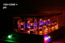
Garage foreourt enclosd
Attachments
richwalters said:zafira1981 said:
But it will be worthy. Plus, there I have a teacher who knows lot of tube amps.
If so..Pick his brains.....while there' there.
A quick and dirty way to avoid excessive surge with relay B+ delay is to use a ballast resistor say 47R-100R 25W on the AC bridge secondary and switch it out with a transistor/ optocoupler. A bit of circuitry is req.
richj
Garage foreourt enclosd
wow that amp is........ PORN......
My amp will be with dark wood and the trafos&tubes mounted on a polished bronze layerwith the trannys painted them black.
I want it to look really good as I'm spending lot of money on it... I live in Argentina, so... parts are far from cheap, imagine for a moment that building this amp will cost you U$s500... but for the money type change, it will cost me like to you u$s1500...
Just to note; the amp in the pic can effectively shove 200W per channel, uses Svet winged C KT88's. I find these tubes are already pushed into the orange glow sector when Iq=60mA at 530V B+ and the anode heating power is reduced when pushed.
This isn't really KT88 performance, the NOS can easily breath 600V at the same quies current without fuss..
On the otherhand JJ Tesla 88 versions show no sign of sweating but give slightly higher thd. Despite the non attractive bulb shape they are more durable.
Building amps in this power class is a law to themselves.
richj
- Status
- This old topic is closed. If you want to reopen this topic, contact a moderator using the "Report Post" button.
- Home
- Amplifiers
- Tubes / Valves
- Help with amp layout