Sure thing; I have it all wired together(no more exploding capacitors), but I dropped one of the output tubes on the floor Friday night; so I will need to wait[for the new set I ordered] before I can see whether or not music comes flooding out in a sweet cascade of electronsLet us know how you do.

Hi Sir Trefor,

That is so sad. Sorry for your loss ......
but I dropped one of the output tubes on the floor Friday night
That is so sad. Sorry for your loss ......
I appreciate your sympathy, sorry you couldn't make it to the funeral ceremony; maybe you could just play "Taps" on your system and pretend to have one by yourself...anatech said:Hi Sir Trefor,
That is so sad. Sorry for your loss ......

Not a big loss, anyway; at least it wasn't one of my smoothplate Telefunken 12AX7s
Proud to report no explosions, at least. an you were right, Anatech, I did have to change the value of the resistor to get the proper voltage.
anatech said:Hi Sir Trefor,
Glad to hear you are working again.
I lost a matched quartet of Westinghouse 6550A when I moved.
-Chris
Hi Chris,
Mine, a couple of NOS RCA 2A3 of 1950's vintage. I didn't keep the remains as it was too sad..
Sir Trefor,
I am glad you were able to the amplifier sorted out, hopefully the tube you lost wasn't anything too special. Annoying and frustrating definitely.

Now to celebrate that the amp is getting sorted out..

Hi Kevin,
It just makes me angry with myself. The skeletons remind me of my mistakes.
Hi Sir Trefor,
We'll be waiting for more reports on your project there. Let us know how it sounds.
-Chris
Ouch!Mine, a couple of NOS RCA 2A3 of 1950's vintage. I didn't keep the remains as it was too sad..
It just makes me angry with myself. The skeletons remind me of my mistakes.
Hi Sir Trefor,
We'll be waiting for more reports on your project there. Let us know how it sounds.
-Chris
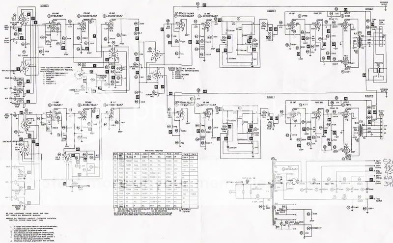
Well, sound comes out; but not that well... I had to turn the volume up ALL THE WAY to hear sound, and even then it's intermittent and distorted. I thought that I might have just connected the speakers wrong, as the silk screening is gone. There are four colors of wire- Black, Brown, Green, Yellow. According to the schematic Z values are black=16, brown=8, green=4, yellow has no denomination- so i assumed it is common. I tried black as common but that is no good.
But I don't think that is the problem.
Thought is was my -15V bias source. I read -14.9 with my meter. Not perfect, but I should hear sound, right?
So, then the question is, if I can actually hear sound at the output, is something expired, or did I more likely connect something wrong?
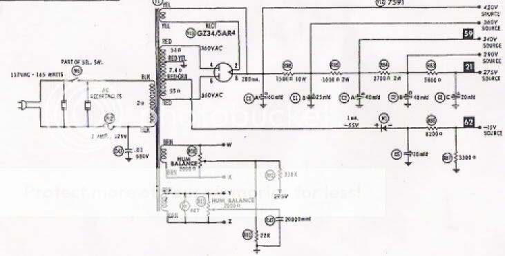
EDIT- Whoa! I just checked the DC voltage at teh supply caps, and they are exobinently high. 520V where it is suppsed to be 420V, 480 where should be 360, 457 where should be 340, 419 where should be 290, 398 where should be 275. Whay are they so high? At pin 8 of the rectifier(5AR4, brand new) I read 502 VDC.
At least I have the exploding thing solved
I had to turn the volume up ALL THE WAY to hear sound, and even then it's intermittent and distorted. I thought that I might have just connected the speakers wrong, as the silk screening is gone. There are four colors of wire- Black, Brown, Green, Yellow. According to the schematic Z values are black=16, brown=8, green=4, yellow has no denomination- so i assumed it is common. I tried black as common but that is no good.But I don't think that is the problem.
Thought is was my -15V bias source. I read -14.9 with my meter. Not perfect, but I should hear sound, right?
So, then the question is, if I can actually hear sound at the output, is something expired, or did I more likely connect something wrong?
EDIT- Whoa! I just checked the DC voltage at teh supply caps, and they are exobinently high. 520V where it is suppsed to be 420V, 480 where should be 360, 457 where should be 340, 419 where should be 290, 398 where should be 275. Whay are they so high? At pin 8 of the rectifier(5AR4, brand new) I read 502 VDC.
At least I have the exploding thing solved
Sir Trefor said:Well, sound comes out; but not that well...
But I don't think that is the problem.
Thought is was my -15V bias source. I read -14.9 with my meter. Not perfect, but I should hear sound, right?
So, then the question is, if I can actually hear sound at the output, is something expired, or did I more likely connect something wrong?
EDIT- Whoa! I just checked the DC voltage at teh supply caps, and they are exobinently high. 520V where it is suppsed to be 420V, 480 where should be 360, 457 where should be 340, 419 where should be 290, 398 where should be 275. Whay are they so high? At pin 8 of the rectifier(5AR4, brand new) I read 502 VDC.
At least I have the exploding thing solved
In the case of output transformers black is usually common and the other three are the 4, 8, and 16 ohm taps. The 4 ohm tap will have the lowest dcr to the black lead, followed by the 8 ohm tap, and finally the 16.
The excessively high voltages and the lack of sound make me suspect that the output tubes are close to total cut off or there is a wiring error and B+ is not getting to the outputs??
I think your first assumption is correct, as I just took out all of the tubes and check the sockets and I read B+ at all of the correct points(pins 1&6 for 12AX7, pin 2 for 7591, etc.); only excessively high(my tube manual says 300VDC max for a 12AX7; I read well over 400). I don't know why the voltages are so high; when installing new capacitors I made sure to use resistors of the correct resistance and wattage. I have wired it correctly, I have double-checked(the only difference I made was that instead of using a single 60uF I had to use a 20 and 40uF wired in parallel). But something is obviously wrong, and I'm not quite sure what I should be looking forkevinkr said:
The excessively high voltages and the lack of sound make me suspect that the output tubes are close to total cut off or there is a wiring error and B+ is not getting to the outputs??
Sir Trefor,
With the rectifier tube in BUT the output tubes (7591) out check:
HT volts on pin 3 (Anode) of each of the 7591 sockets with respect to pin 5 (cathode) - Don't worry too much if this is quite high, around 500 or so volts UNLESS you are using 450V or lower rated electrolytic power supply caps.
- in which case turn off immediately and report so we suggest changes.
Check volts on pin 6 (grid1) of each of the 7591 socket with respect to pin 5 (cathode). You should read -15V , the bias voltage. If NOT do not proceed until you have found out why not and fixed it.
If bias volts on all sockets reads OK then plug in the 7591 tubes and power up. After 30 seconds (when the output tubes start to conduct) check your HV again. It should now be down around 420 to 450 volts.
If its 420 everything is OK. If its 450 then I would adjust that R you changed to get the bias voltage down to -15V so that you get more like -21 volts. -15V is just not enough when you have 450V on the anodes.
If you are stll in strife - scan your schematic and post it and we'll try to see what might be wrong.
Cheers,
Ian
Measure the filament voltages present on the 12AX7A sounds like there may be a wiring error. Those plate voltages make me believe that the filaments are not lit. The filaments are powered by the same rectifier that provides bias to the output stage and if not connected for some reason the bias voltages will be WAY high.
I would use a ballast lamp to limit current if there is an internal fault so that you do not loose the power transformer.
An isolation transformer is a good idea if you have one, although the power transformer provides adequate isolation if you don't have one and are careful. A GFI at your bench is also a good idea..
- Status
- This old topic is closed. If you want to reopen this topic, contact a moderator using the "Report Post" button.
- Home
- Amplifiers
- Tubes / Valves
- Checklist to observe before applying the mains