Could anyone please help me out figuring the circuit's output impedance and gain?
What type of circuit is this, and the formulas for the calcs?
Here's the link: www.b-kainka.de/bast174.jpg
Thank you very much
Francis
What type of circuit is this, and the formulas for the calcs?
Here's the link: www.b-kainka.de/bast174.jpg
Thank you very much
Francis
ECC86
Hi,
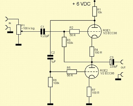
First of all this is a headphone amp using a low voltage tube that was used in car radios.
It is a twin triode that looks exactly like an ECC88 (folded anode construction).
The circuit can be described as an SE OTL and is in fact a White cathode follower.
Without any calculations done I estimate the output impedance at 10 to 15 Ohm.
It has no gain but fed from a CDP it should be O.K.
In fact this a similar circuit to what I would use but then with a 6AS7G.
I would put a 10 K resistor across the output since the output cap would charge and put a voltage at the output without the headphones connected.
Cheers,")
Hi,
First of all this is a headphone amp using a low voltage tube that was used in car radios.
It is a twin triode that looks exactly like an ECC88 (folded anode construction).
The circuit can be described as an SE OTL and is in fact a White cathode follower.
Without any calculations done I estimate the output impedance at 10 to 15 Ohm.
It has no gain but fed from a CDP it should be O.K.
In fact this a similar circuit to what I would use but then with a 6AS7G.
I would put a 10 K resistor across the output since the output cap would charge and put a voltage at the output without the headphones connected.
Cheers,
NPN Push-Pull with TUBES/transistors
A PUSH PULL arrangment with 2 NPN devices
If you compare your TUBE-circuit with the transistor cicuit
you see the similarity.
The main component is the Cap, that goes to the input of the lower TUBE/transistor.
At a positive signal goes more current in the upper tube.
This makes more voltage over the anode-resistor,
this "pushes" down the cap (gives a negative pulse through cap)
the is connected to gate of lower tube.
That makes the lower tube "turn off" so less current
goes through that tube.
So result is, that when more current goes in upper tube
less current goes in lower tube.
So in fact they work in push-pull.
And you can say they do half the job each,
which is good for distortion.
(see D.Self's measurment curves of harmonic distortion)
Without that Cap, the lower transistor would just be a current source.
so the amplifier would be PURE SINGLE END.
/halo
------------------------------------------------------------
DESIGN WITH DISCRETE TRANSISTORS - the complementary feedback pair /D.Self
A PUSH PULL arrangment with 2 NPN devicesIf you compare your TUBE-circuit with the transistor cicuit
you see the similarity.
The main component is the Cap, that goes to the input of the lower TUBE/transistor.
At a positive signal goes more current in the upper tube.
This makes more voltage over the anode-resistor,
this "pushes" down the cap (gives a negative pulse through cap)
the is connected to gate of lower tube.
That makes the lower tube "turn off" so less current
goes through that tube.
So result is, that when more current goes in upper tube
less current goes in lower tube.
So in fact they work in push-pull.
And you can say they do half the job each,
which is good for distortion.
(see D.Self's measurment curves of harmonic distortion)
Without that Cap, the lower transistor would just be a current source.
so the amplifier would be PURE SINGLE END.
/halo
------------------------------------------------------------
DESIGN WITH DISCRETE TRANSISTORS - the complementary feedback pair /D.Self
Attachments

THE JOY OF HALO.
Hi,
If you look hard enough you will notice that a lot of the things done today with solid state devices are in no way different from what was done with valves over fifty years ago.
The only thing you don't have with valves is complementary pairs.
FYI,even to this day a lot more valves are used than one may imagine.
Think about the magnetron in your kitchen and you might get an idea.
Cheers,
LOAD
Hi,
Any headphone should work O.K. with this circuit as long as the impedance does not drop below 30 Ohm.
Gain should 0.97 for the White CF.
Load for this should ideally be a factor higher than the Zo of the amp.
For headphone use it is not all that critical though.
Cheers,
Hi,
Any headphone should work O.K. with this circuit as long as the impedance does not drop below 30 Ohm.
Gain should 0.97 for the White CF.
In fact for any OTL amp, depending of it's output impedance?
Load for this should ideally be a factor higher than the Zo of the amp.
For headphone use it is not all that critical though.
Cheers,
Some calculations using correct values: Zo=40 ohms (it always gives me 0.40, decimal values, dunno if its ok);
Gain:0.93
I'm using the formulas from tubecad.
If i remove R4, will it harm the circuit? It will look more like the WCF basic circuit.
Any tips on how to improve the gain a bit further ? Increase R1 for, say, 15K?
If i add a pre-gain stage, will it have enough distortion for guitars? Just a tought...
Thanks!
PS: got some PCBs on the bench for etching. now, for the tubes and stuff...
- Status
- This old topic is closed. If you want to reopen this topic, contact a moderator using the "Report Post" button.
- Home
- Amplifiers
- Tubes / Valves
- Help with a circuit