Hello,
I'm playing with a PP amplifier project, using 2 6AS7 as output tubes.
Due to the high voltage swing they need on grid (mu<2), I was thinking to try to use an interstage transformer, maybe with something like 1:4 ratio.
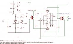
I ended up with THIS schematic: it would be a LTP with the interstage trafo connected as plate load; no calculation done, just the idea.
It should be very linear, and with a small amount of feedback from the interstage trafo secondary winding (on the LPT inverting input) should have small distorsion.
What do you think of this solution?
I'm also thinking to use a siomilar topology (LPT) also for the output stage with 6AS7, but I've never seen anything like this for now, so probably thisis not agood idea.
Ciao,
Giovanni
I'm playing with a PP amplifier project, using 2 6AS7 as output tubes.
Due to the high voltage swing they need on grid (mu<2), I was thinking to try to use an interstage transformer, maybe with something like 1:4 ratio.
I ended up with THIS schematic: it would be a LTP with the interstage trafo connected as plate load; no calculation done, just the idea.
It should be very linear, and with a small amount of feedback from the interstage trafo secondary winding (on the LPT inverting input) should have small distorsion.
What do you think of this solution?
I'm also thinking to use a siomilar topology (LPT) also for the output stage with 6AS7, but I've never seen anything like this for now, so probably thisis not agood idea.
Ciao,
Giovanni
I'm far from knowledgeable enough to give you advice - I leave that to others. My questions would be:
1) do you need a C2?
2) if R10 is a grid stopper it should be on the tube side of the grid leak R3, and one on the other grid too, no?
3) should R1 and R3 be going to ground directly?
4) why R2?
5) why the feedback to grid 2?
6) why the plate resistors R16/17 AND the transformer? Won't the transformer connect in simple push-pull?
7) I haven't seen this arrangement of resistors and bypass caps before - what's the reason for it?
Cheers, Andy Evans
Thank you Andy Evans,
1) I think so, cause the V1A input is not related to ground
2) Right. My mistake.
3) if they go to ground, I would need an additional negative supply (at least -12V) for the CCS.
Probably you're right and that one is the right way to go.
4) To bias the two valves IF R1 and R3 are not connected to ground
5) it is a sort of local feedback; it was there because in the first time I drawmn only the driver stage, and would like to try it without output load
6) I don't know. it seems right to me, but I have to take my Morgan Jones "valve amplifier" and calculate it.
7) Cause the output tubes (6AS7) are known to be not very matched, so this is an idea to keep them as balanced as possible.
This is only an idea, of course it has to be developed.
Ciao,
Giovanni
I have done something very similar using 6AS7's . My experience with the interstage transformer (I used mains toroids which are suboptimal for the job) is that you will have zero chance of success if you try to use a step up transformer. The step up will amplify the interwinding capacitance of the interstage and then add on the miller capacitance. In the end I had to push 40mA of drive to get satisfactory frequency range from the interstage.
Think about using your interstage to phase split at the front end. This should prefereably be a step down to make it very easy to drive. Then feed it into a LTP with CCS. This may be adequate to drive the 6AS7, or you may need another stage. Consider a ECL86 as a two stage drive. This is what I am considering doing with 807's - with plate to plate feedback on from the pentode to the 807 to eliminate the need for global feedback (a big no no with interstage transformers due to phase shift issue).
Another thing - these transformers tend to ring so benefit from light loading on the secondaries . Applying feeback as you suggest presents an uneven load on the secondaries and will have a negative impact on balance. Again I tried it and then dropped it.
I have attached my schematic to show you what worked for me.
Attachments
Nice project, Shoog!!!
I really like it; indeed, after I opened this thred, during my trip back home from my work, I thinked to use something very similar to what you did, a parafeed driver for the interstage transformer.
But since I have a lot of 6N6P valves I would try them as drivers...
Did you built it? How does it sound?
Ciao,
Giovanni
Its my main amp at the moment.
I took it to a local small DIY meet at the weekend and it sounded the best of the bunch (though there wasn't much competition). It has good pace, excellent micro level detail and a lovely sweet tone. The only real issue it has is a little bit of treble softness due to the interstage.
Did you spot that it has a differential output stage.
The output has less than unity gain, but it only needs a modest 60Vpp of drive to achieve about 7watts.
Shoog
I have been experimenting with a cathode follower output stage. I have tried several different tubes, but currently there are 6AS7's in the sockets. These guys need 400+ volts of drive. I wired up an LTP circuit with a Triode Electronics driver transformer IN PLACE OF the plate resistors. The CCS is returned to -15 volts. R2 is not needed, the CCS does the job. R1 and R3 go to ground. There is no C2. and C1 goes to ground (no feedback). This concept works great UNTIL I connect up the 6AS7, then the distortion gets ugly. I am considering a different topology, I just don't know what yet.
I was looking at your schematic, Shoog:
What is the function of C2, C3, C6, C7 & C4 (I hope to read well, the components name are not really clear)?
Ok, they connect the two cathodes, creating a path for AC signal; but why?
Again: why two CCS, instead of using only one in the tail for both the output triode (a true LTP)? Which is the advantage of using them?
Ciao,
Giovanni
The two CCS keep the current balance in the output transformer to within 1mA which is essential when using toroids, and a good idea anyway.. No adjustment is ever needed.
The cathodes of the 6AS7's are not referenced to earth at all, and the caps you mention are there to allow the two triodes to talk to each other. In this way it performs as a true differential output stage. The 1Meg resistor is there to keep the caps correctly biased.
C4 bypasses the bigger caps at high frequencies.
C2 & C3 are unusually large because they are in series and so only represent a 1000uf path for the signal.
A single CCS would allow you to eliminate all of the cap network which on the surface of it would be a huge advantage. Unfortunately you would have to take into account the current imbalance and introduce a manual current balancing network. I opted for the zero adjustment option because i'm lazy that way. I don't think there are many sonic penalties for setting it up in the way I have as the differential nature seems to perform error correction on cap based distortion (that a guess on my part).
Shoog
- Status
- This old topic is closed. If you want to reopen this topic, contact a moderator using the "Report Post" button.
- Home
- Amplifiers
- Tubes / Valves
- LTP with interstage trafo