Hi !
You do that in a similiar way as for triodes. You pick your curves and draw a suitable loadline and pick a symmetrical operating point.
The abilty of a pentode's anode to control the current is very low, resulting in an extremely low punch-through effect and an accordingly very high µ. Result is that the amplification is mostly depending on the Load on the grids ability to change the current --> gm. Short equation: A = S*Ra
Screen grid voltage must be fixed to cathode n a kind of way. Either a cap from screen to ground or a gas stabilizing tube does this job perfectly.
A good pentode working in inductive load is one of the best stages ever. With a high gm tube and larger currents you are able to drive evrything. A C3M can drive a 300B without problems and with very low distortion.
I always prefer pentodes. It's the more decent, natural und dynamic sound. Not that warm, plentyful triode sound with the overemphasized midrange and voices.
Regards, Simon
To expand a little bit on Simon's reply... there is maybe an additional degree of freedom as compared with a triode, which has more-or-less fixed voltage gain.
You can pick the plate load based on desired gain (high = high gain, low = low gain), or on desired Zout (low=low, since Rp is typically very high, Zo is dominated by Rl). Of course you also have to consider the B+ and plate current as well.
For example, for a driver stage where you want low output impedance, you can pick the lowest resistance that gets you a reasonable voltage swing.
Or, for a mic preamp, you might want the highest load you can do within B+ limitations to get really high gain.
Yet another choice is to optimize for lowest distortion, by eyeballing the curves. Some pentodes can be amazingly linear operated over the right spot.
Of course, usually you wind up doing a compromize between all of these things.
Pete
Thanks, that's very helpful. Additionally, I seem to see the screen connected to B+ through a largish resistor (50K on up) and bypassed to ground through a smallish cap (100n or so.) Any tips on picking those, or other ways to connect things up? And, what exactly is that resistor doing. Does it keep the screen at a high voltage (with no current flowing), or does it drop lots of volts with a small amount of current flowing, and iof so, can it be connected to ground instead.
My current application is a guitar amp, so distortion is not a bad thing, I don't think.
Rl is the load?
My current application is a guitar amp, so distortion is not a bad thing, I don't think.
pmillett said:since Rp is typically very high, Zo is dominated by Rl). Of course you also have to consider the B+ and plate current as well.
Rl is the load?
With small signal pentodes, the screen current is usually about 20% of the plate current. A typical plate load for a pentode might be 100k. The screen resistor might be in the region of 470k to 680k, to provide a screen voltage that is in the region of the plate voltage but somewhat lower.I seem to see the screen connected to B+ through a largish resistor (50K on up) and bypassed to ground through a smallish cap (100n or so.) Any tips on picking those, or other ways to connect things up? And, what exactly is that resistor doing.
Also, the screen needs to be AC-connected (decoupled) to the cathode. With a fully-bypassed cathode bias resistor, the screen can be decoupled through a capacitor to ground; however, if some or all of the cathode resistor is not bypassed (e.g. where global NFB is is injected into the cathode), the screen needs to be decoupled to the cathode itself. A suitable sized cap for this purpose would be ~0.1uF. The quality of this cap is important and its value can have a strong influence on low frequency stability if the pentode is inside an NFB loop. It's one more thing you may have to fiddle with.
dsavitsk said:Thanks, that's very helpful. Additionally, I seem to see the screen connected to B+ through a largish resistor (50K on up) and bypassed to ground through a smallish cap (100n or so.) Any tips on picking those, or other ways to connect things up?
If you have the characteristic curves, you can determine what the screen current will be, and so you simply use a series resistor to drop the Vpp to Vsgsg. If using a fully bypassed cathode bias resistor, my own preference is to stiffen the screen voltage with a voltage divider, especially if there's gonna be a significant plate current swing. A series screen resistor'll convert any pentode into a (more or less) remote-cutoff-type device. Not a good thing for low distortion.
An externally hosted image should be here but it was not working when we last tested it.
(Unless that's what you need, as in the IF strip of a receiver.)
If the cathode isn't bypassed (pentode cathode follower, as in the upper half of a Kimmel) then screen voltage swing is essential if you want to prevent a type of ultralinear operation that will reduce gain and raise Zo. In that case, a series resistor + healthy screen coupling to the cathode is required.
The screen impedance is pretty up there, so a big capacitor isn't required. Guesstimate it as: Rsg= (Vsgk/Isgq || Rsg), and scale the capacitor according to your low frequency requirements.
There are other cases where you might have to tailor the screen bypass for other considerations since the screen is kind of a control grid, and the RC combination can insert an extra pole into the transfer characteristic of the amp, with sometimes unexpected results.
My current application is a guitar amp, so distortion is not a bad thing, I don't think.
Go with the simple series dropping resistor and see what happens. If it sounds too gawdawful, then try stiffening up that screen voltage.
One thing to keep in mind with pentodes....You want to stay in the SATURATION region for the entire load-line swing....
The SATURATION region is the part of the IV curve that goes horizontal after the knee or close to that....It has a small slope...that slope is the plate resistance and it is quite high...An ideal pentode would have totally flat horizontal curves indicating a perfect current source of infinite impedence...
Well the key curve to look at is your 0v bias curve...since this is the end of the line for your load-line swing.....assuming your staying away from driving for grid current...
YOu want to maximize your AC swing for the must current and most voltage..so when the load-line approches the 0v bias curve cross it to the right of the knee and make sure your still in Saturation.... if your plate load number is too big you will interect you 0v bias curve when it is still in the TRIODE region when it is almost vertical....this will not only introduce more non-linearity, but the plate resistance of the pentode will drop low and cuase more issues...
Chris
cerrem said:if your plate load number is too big you will interect you 0v bias curve when it is still in the TRIODE region when it is almost vertical....this will not only introduce more non-linearity, but the plate resistance of the pentode will drop low and cuase more issues...
Chris
(See attached)
This may or may not be a problem. If doing something like a DC voltage amp for a regulator, then dunworryboudit: the Vgk will always stay very close to the nominal bias value. That's how the thing works: it always tries to move the voltage to maintain that particular value of voltage differential.
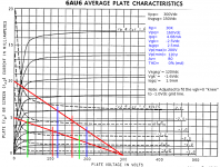
If you can't be certain that some idgit won't connect to some source that outputs more than 2.5Vp, then you can either do one of two things: draw a loadline that goes through Vgk= 0 while still within saturation. Here, you wouldn't want to do that because we've already got one helluvagood loadline there. (The one in Blue, not the Green one.)
Now, it would be nice if we could replace the Vgk= -1.0Vdc line with the Vgk= 0V line. Since this particular characteristic was made against Vsgk= 150Vdc, we can do just that. If we want to drop the whole thing by one volt, pick off the loadline Ip at a Vgk= -4.0V. Then go to the "Average Transfer Characteristic" chart that plots Vgk against Ip at various screen voltages. Find out where the -3.0V line intercepts the plate current for Vgk= -4.0V @ Vsgk= 150V. By means of interpolation, this comes quite close to a Vsgk= 120Vdc (actually something like 119. something, something, something but don't worry about that since VTs aren't all that accurate, and VT circuits tend to be rather "forgiving").
Once you have your new screen voltage, next find from the chart the Vgk that'll give the original design Ipq for the new Vgkq bias.
This should preserve the original design performance (or come close enough for tweaking the Vsg for minimal THD if that's what you want) and close enough so that you won't be poofing screens by operating too close to the "triode" region.
Attachments
I think of pentodes liking constant voltage, whereas triodes "like" constant current. Pentodes generally have lower distortion (and particularly lower odd harmonics) with smaller plate loads. Of course, with constant voltage you get no output.
I choose the smallest plate load that gives me enough output voltage swing for my application. Lower screen voltages generally produce less distortion, but then there is less input headroom. It's a balancing act. And I recommend trying VR tubes for the screen supplies. They were made for this service and work (and sound) very well.
Unlike what some others have advised I try to stay COMPLETELY away from the knees in the curves. This usually means higher plate voltages and smaller plate resistors (and hence lower gain) than what is recommended as an operating point in the data sheets.
The data sheets try to maximise the gain by aiming the load line at one of the knees. I try to aim the high current end of the loadline as near to the flat part of the 0V curve as possible. If you don't need the input headroom this gives, use a lower screen voltage.
I'm sure some will disagree with the above method, but I say try it. I think you'll like it.
Totally concur with Jeff, this is pretty much the process I follow when working up a pentode for input duty - which I commonly do. Stable screen grid voltage is high priority (VR's are great and simple to use), stay away as far as possible from the knee with the smallest useable load for required gain (ie as vertical a load line as suitable for the gain required) and try to keep max grid voltage to around -1V max (not always possible) to stay away from decreasing input impedance as grid current starts.
Used this way pentodes can do great service. I have 3 amps set up this way using 77's, 6J7's and 24A's as input pentodes/tetrodes.
Used this way pentodes can do great service. I have 3 amps set up this way using 77's, 6J7's and 24A's as input pentodes/tetrodes.
Reviving an old thread ...
Just how low can a plate load on a pentode go and what does this do to Gm? For instance, on a 5879 (datasheet), a load of 2K5 would result in a gain of about 2.5 or so. Is this reasonable to do? And, does this cause gm to go way up as the change in current is high for a small change on the grid?
Just how low can a plate load on a pentode go and what does this do to Gm? For instance, on a 5879 (datasheet), a load of 2K5 would result in a gain of about 2.5 or so. Is this reasonable to do? And, does this cause gm to go way up as the change in current is high for a small change on the grid?
dsavitsk said:Just how low can a plate load on a pentode go and what does this do to Gm?
Depends. Reducing the plate load will reduce the gain and the possible output voltage swing. How much of both do you need? That'll usually set the floor for Rp values.
For instance, on a 5879 datasheet, a load of 2K5 would result in a gain of about 2.5 or so. Is this reasonable to do? And, does this cause gm to go way up as the change in current is high for a small change on the grid?
It might be reasonable to do that especially if what you're trying to achieve is a wideband response. When combined with Co + Ci (next stage) + Cstray, a small Rp will give a higher f(h) cutoff. Getting Rp down as far as possible is used in the design of video amps, for example. Of course, you're not gonna get the full 4.0MHz BW you need just from reducing Rp, and so you'll require compensating coils to extend the BW. (If using BJTs, you can reduce the Rc to 50R -- 100R, still have useable gain, and BWs into the VHF region without needing any compensating coils.)
Miles Prower said:Depends. Reducing the plate load will reduce the gain and the possible output voltage swing. How much of both do you need? That'll usually set the floor for Rp values.
But assuming I don't need much swing or gain, say for preamp duty, but do need a low output Z, then a plate load in the 500R to 1K range could be reasonable?
For another question, I am using some 6688's as triodes which means that g2 is tied to the plate and g3 is internally tied to the cathode. On the pentode curves, they say that g2 is at 150V and g3 is at 0V. Now, I have 150V on the plate, which means that I have 150V in g2 as well -- so what has made this magically switch from pentode to triode? The ony differences I see in the datasheet (http://www.mif.pg.gda.pl/homepages/frank/sheets/030/e/E180F.pdf) are that the voltages are slightly dfferent (150 & 180 for pentode, 150 & 150 for triode.)
dsavitsk said:But assuming I don't need much swing or gain, say for preamp duty, but do need a low output Z, then a plate load in the 500R to 1K range could be reasonable?
Again, it depends. A better solution might be to use a cathode follower for a Lo-Z output.
For another question, I am using some 6688's as triodes which means that g2 is tied to the plate and g3 is internally tied to the cathode. On the pentode curves, they say that g2 is at 150V and g3 is at 0V. Now, I have 150V on the plate, which means that I have 150V in g2 as well -- so what has made this magically switch from pentode to triode? The ony differences I see in the datasheet
What makes a pentode into a triode is the fact that both the plate and screen see the same AC voltage. Now, if you were to run the 6688 with Vsgsg= Vpp, and you maintained the screen at AC ground, then it would still operate just like a pentode. Indeed, that is frequently done in cases where you don't have a whole bunch of voltage, such as a TV IF strip that runs off a power xfmr-less DC supply.
... . . . .
A good pentode working in inductive load is one of the best stages ever. With a high gm tube and larger currents you are able to drive evrything. A C3M can drive a 300B without problems and with very low distortion.
I've been thinking about the C3M to drive a 6336 and am interested in your experience with inductive loads on pentodes. I'm guessing the L value would need to be pretty high. Can you say more about your experience?
Thanks
Might have a look at some of the Lundahl chokes like the LL1667/1668. I've not tried this but can see no reason why it would not work provided that there is not excessive capacitance in the choke. Note that the resistance in the grid circuit will define the gain based on value chosen and there may be some LF interaction between the choke and coupling capacitor. Best to model in spice.
Might have a look at some of the Lundahl chokes like the LL1667/1668. I've not tried this but can see no reason why it would not work provided that there is not excessive capacitance in the choke. Note that the resistance in the grid circuit will define the gain based on value chosen and there may be some LF interaction between the choke and coupling capacitor. Best to model in spice.
Alas, I mostly work on Mac and have never learned to use LTSpice beyond occasional noodling with stock library parts. I got the impression from Simon's post that he had experience with the topology and was looking to hear what he had discovered. It was an old post though and perhaps he has moved on in his thinking.
The inductance also needs to be sized to be a multiple of the chosen load at the lowest frequency of interest. 10K is borderline, 100K is out of the question.
dave
I was thinking of starting with the oft' quoted 12K , putting the first multiple at ~190H for 20Hz. Whatdaya say Dave? is 2x worth looking at ?
- Status
- This old topic is closed. If you want to reopen this topic, contact a moderator using the "Report Post" button.
- Home
- Amplifiers
- Tubes / Valves
- Pentode Plate Load