I got a pair of 6688/E180Fs, a transformer with 190-0-190, 50V tap, and 3.15-0-3.15, 2 120H 36mA plate chokes and a used Hammond aluminium chassis. Can I put together a nice sounding line stage out of this without much extra cost?
If so, suggestions on operating conditions please? I can't seem to find its triode curves anywhere... that is if triode connection are the way to go if I read correctly... Also is this a lot of gain for a line stage?
cheers!")
If so, suggestions on operating conditions please? I can't seem to find its triode curves anywhere... that is if triode connection are the way to go if I read correctly... Also is this a lot of gain for a line stage?
cheers!
pengboon said:I got a pair of 6688/E180Fs, a transformer with 190-0-190, 50V tap, and 3.15-0-3.15, 2 120H 36mA plate chokes and a used Hammond aluminium chassis. Can I put together a nice sounding line stage out of this without much extra cost?
If so, suggestions on operating conditions please? I can't seem to find its triode curves anywhere... that is if triode connection are the way to go if I read correctly... Also is this a lot of gain for a line stage?
cheers!
it will be too much gain,even in triode- if I remember correctly- in range of 40 to 60;
you have two ways to do this- anode follower with choke load or-even better- WOT stage,parafeed or not.
btw -awesome toob.......
no!!
dreky toob,send that to me for proper disposal !
I have my headphone amp running 6688's right now. They are quite nice -- more detailed than 5842's, but less full sounding perhaps. I have some 7788's on the way to try too.
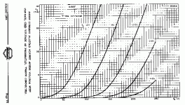
Search is failing me, but here are some curves that were posted when I asked the same question a while back.
Search is failing me, but here are some curves that were posted when I asked the same question a while back.
Attachments
Zen Mod,
I'm probably going to do it anode follower with choke loading. Don;t think I want to spend on OPT at this point of time. Any nice operating points to recommend?
Alexg,
I know you are using it for DAC, but have you compared GG vs anode follower for line-stage?
AndreasS,
Thanks for the reminder, should be sufficient for regular 2V output from CDP, phono right?
pengboon said:
Alexg,
I know you are using it for DAC, but have you compared GG vs anode follower for line-stage?
Unfortunately I have not compared GG vs anode follower for line-stage.
But I would be very interested on the result of what you will be doing, for I have some 6688 tubes and would like to experiment with them.
soundbrigade said:How about a mu-follower, using the pentode as CCS??
Why a high-transconductance pentode for the upper tube? It is difficult to stabilisize the operation point, because you can use only a small cathode resitor.
Andreas
If you don`t need gain,,, a choke loaded cathodefollower?
http://www.tubecad.com/2007/04/blog0104.htm
http://www.tubecad.com/2007/04/blog0104.htm
pengboon said:Zen Mod,
I'm probably going to do it anode follower with choke loading. Don;t think I want to spend on OPT at this point of time. Any nice operating points to recommend?
................
sorry ; I search everywhere,but I just can't find some xerox copies I have with needed data.....
AndreasS said:
Why a high-transconductance pentode for the upper tube? It is difficult to stabilisize the operation point, because you can use only a small cathode resitor.
Andreas
But on the other hand, a high transconductance tube offers a lower output resistance. Furthermore the E180F can handle a high current (for its size) which allows to drive low impedances.
This also helps to flatten the bottom tube's loadline (in an AC point of view of course..)
Regards, manta
Peter M. said:If you don`t need gain,,, a choke loaded cathodefollower?
http://www.tubecad.com/2007/04/blog0104.htm
Is the difference in anode and cathode followers only in gain?
The CF in the link don't seem to require a choke load? Am I missing something here?
cheers!
the_manta said:
But on the other hand, a high transconductance tube offers a lower output resistance. ...
Hi Simon.
pls. give your µ-follower a high-impedance load

Regards Andreas
AndreasS said:
Why a high-transconductance pentode for the upper tube? It is difficult to stabilisize the operation point, because you can use only a small cathode resitor.
Andreas
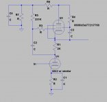
If you use fixed bias on the upper tube rather than cathode bias it is very easy to control the operating point and it also gives you freedom to use a much larger cathode resistor with the upper tube. I use mu follower based active loads configured this way and it works very well. Get the grid bias from a well decoupled voltage divider off of the B+. Imagine a cross between a cascode amplifier and the mu follower. Pentode connection should yield very close to ideal ac performance. From an AC perspective if you tap off of the upper tube cathode it is a mu-follower, if you tap off of the plate of the lower tube it behaves much like a ccs for the ac signal only - adjustment of plate voltage on the lower tube becomes very easy for either case, just by varying the voltage divider ratio feeding the upper grid.
You can use much lower mu triodes in place of the 5842, and select a pentode or triode that performs well at the operating current of that triode or you can add a resistor to ground from the cathode of the follower section (aka augmented CF) to increase the current through just the follower.
The voltage divider comprised of C4 and R6/R7 can be shared between channels.
Note while probably not entirely original I have posted this circuit for personal use only.
Attachments
Hi Kevin,
Many thanks for your suggestion. R5 is parallel (for AC) the load resistance of the lower tube; this impairs the advantage of the use of a high transconductance pentode as upper tube.
The size of R5 (grid resistor) is particulary limited for high transconductance tubes.
Regards Andreas
Many thanks for your suggestion. R5 is parallel (for AC) the load resistance of the lower tube; this impairs the advantage of the use of a high transconductance pentode as upper tube.
The size of R5 (grid resistor) is particulary limited for high transconductance tubes.
Regards Andreas
Hi Andreas,
Yes your point about R5 is quite true, however it can be as big as permitted by the tube specification. I have used up to 1M in some instances without issues, (not with these pentodes!) and in the case where the rp of the triode is around a couple of Kohm this is insignificant. Still the bootstrapping effect of the pure mu-follower is absent, hence I wouldn't recommend doing this with tubes having very high rp - usually they are much lower current so the issue I designed this to address is then irrelevant.
OT: I modeled a cascode based design with one of these on top to drive an 845, and initial bench experiments indicated that it would work. How good it would sound I have no idea. The 900V supply required made it impossible to test properly with the supplies I have on hand. (It was designed to share plate supply with the output stage.)
Hi folks !
Andreas has already pointed it out. The advantage of the µ-follower falls apart with that additional resistance.
And for general discussion:
My current µ-follower looks like this. It's going to be a PS1 Buffer stage. The EL802 is nice t00b with a gm of 40mA/V
You mean the low impedance load will reduce the CF's amplification and the advantage of the µ-follower will fall apart ?
Regards, Simon
Andreas has already pointed it out. The advantage of the µ-follower falls apart with that additional resistance.
And for general discussion:
My current µ-follower looks like this. It's going to be a PS1 Buffer stage. The EL802 is nice t00b with a gm of 40mA/V
An externally hosted image should be here but it was not working when we last tested it.
AndreasS said:
Hi Simon.
pls. give your µ-follower a high-impedance load
Regards Andreas
You mean the low impedance load will reduce the CF's amplification and the advantage of the µ-follower will fall apart ?
Regards, Simon
I had some free time (finally!) over the weekend and I attempted to salvage some of my excess components to build a line stage, those components are listed on my first post in this thread.
Anyway, I decided to go with the common cathode with 120H choke on plate first. I also have a pair of VR150s which I may add later on! Problem is, I can't stop it from humming! Does the 6688 require DC heaters? I'm using AC (6.1V) with ferrites at the sockets, one terminal grounded. Grid stopper is 390R. 100k pot before that. 160R on cathode, 47R between anode and g2 B+ of about 130+V, output cap from anode of 0.47uf. g3 and other connections of g2 and cathode are not connected. The PSU is a simple CRCRCRCRC, I tried putting some SS regulator to no avail too.
It was fine when it was a GG stage... Any suggestions? thanks!
Anyway, I decided to go with the common cathode with 120H choke on plate first. I also have a pair of VR150s which I may add later on! Problem is, I can't stop it from humming! Does the 6688 require DC heaters? I'm using AC (6.1V) with ferrites at the sockets, one terminal grounded. Grid stopper is 390R. 100k pot before that. 160R on cathode, 47R between anode and g2 B+ of about 130+V, output cap from anode of 0.47uf. g3 and other connections of g2 and cathode are not connected. The PSU is a simple CRCRCRCRC, I tried putting some SS regulator to no avail too.
It was fine when it was a GG stage...
Any suggestions? thanks!If you're of the opinion that the AC heater voltage is in charge of the hum then there is an easy test to prove that.
Disconnect the heater voltage for a few seconds and listen. The heat in the cathode will last for that short time so that Anode current still flows. If you dont hear any hum now then you know it was generated by the heater voltage.
But IMHO the hum is induced in the chocke by any magnetic field on your workspace. Try moving the choke away from the mains transformer or rotate it taht the cores don't face their ways of magnetic flux
regards, Simon
- Status
- This old topic is closed. If you want to reopen this topic, contact a moderator using the "Report Post" button.
- Home
- Amplifiers
- Tubes / Valves
- 6688/E180F line stage?