Guys,
Maida's design calls for a 20 K./5 W. pot. I'm having difficulty sourcing the part. My application of the regulator is in refurbing OLD Fisher mono phono preamps (schematic) attached. The filtered B+ will be about 150 V. The regulated rail will be 110 V. per the schematic.
I'm a NOOB, when it comes to the "care and feeding" of regulated PSUs. The ability to adjust down to 1.2 V. is unnecessary in this case. My thinking is to put a 15 KOhm fixed resistor in series with a 5 KOhm pot. Is my thinking correct?
TIA for any info. provided.
Attachments
If it were me, I'd tell myself, "Self, it really doesn't matter if the voltage there is 148 or 152. And the voltage spread on LM317 tends to be pretty low- the equations for the output voltage get me within a percent or so every time. So just calculate the proper value of fixed resistors, and go with that, avoiding running DC through a pot wiper."
That's what I'd tell myself.
That's what I'd tell myself.
Hi Eli,
I've had pretty good luck with the LM317, for your application the resistor between ref and out could be about 1.21K (~1mA) which makes selecting the resistor for setting the output voltage really easy.
A 143K resistor would give you about 149V depending on regulator and resistor tolerances. The resistor dissipation is about 150mW, but due to the voltage involved should at least be a 1/2W RN60 type.
Using a minimum of 1mA in the resistor string I have not observed strong temperature dependence in the output voltage, and relatively consistent voltage setting over a spread of parts. The reference current is typically about 100uA, good design practice dictates a string current at least 10X this to minimize errors due to the reference current.
I've had great luck with resistances in that higher range, too (drawing about 1mA). Giaime, the reason the resistances are so low in the app note is that he's trying to ensure that the specified minimum LM317 current is being drawn at all times. If you use larger resistors for lower dissipation, you must have the Maida loaded at all times or it will go out of regulation.
Brian Beck said:I've had great luck with resistances in that higher range, too (drawing about 1mA). Giaime, the reason the resistances are so low in the app note is that he's trying to ensure that the specified minimum LM317 current is being drawn at all times. If you use larger resistors for lower dissipation, you must have the Maida loaded at all times or it will go out of regulation.
I've read this too, but have not seen issues even with load currents of 1mA with any LM317 I've purchased since the early 1990's.. Pays to check though, because there are quite a few variants of the LM317 and not all of them are likely to behave as well when lightly loaded.
Recent low drop out versions of the LM317 apparently have much worse ripple and noise rejection than the original version which fortunately is still readily available.
Hello Kevin! ")
Yes, that's absolutely true. As a matter of fact, my 317s (yes, there are many versions out there! All different) draw 50uA from the adjust pin, and I never observed great change in voltage with temperature with a string current of 2x-3x the adjust current.
Most of the work is finding the right combination of standard value resistors: most of the time 1W ones aren't available in 1% precision.
Of course if you don't load it (and you have chosen high valued resistors), the regulation fails, but mr. Duttman asked about a regulator for a very simple valve circuit, not a full-blown computer controlled HV bench supply
Edit: remember to put the mosfet on an heatsink! Its voltage drop is almost the full drop of the regulator (leaving 5-8V for the LM317), and the whole current must pass there, so make calculations and choose an appropriate heatsink. Note that the mosfet can have the metal tab at a high voltage: insulate it, or do like me, dismantle old power supplies to find those lovely japan full-insulated mosfets
kevinkr said:Using a minimum of 1mA in the resistor string I have not observed strong temperature dependence in the output voltage, and relatively consistent voltage setting over a spread of parts. The reference current is typically about 100uA, good design practice dictates a string current at least 10X this to minimize errors due to the reference current.
Yes, that's absolutely true. As a matter of fact, my 317s (yes, there are many versions out there! All different) draw 50uA from the adjust pin, and I never observed great change in voltage with temperature with a string current of 2x-3x the adjust current.
Most of the work is finding the right combination of standard value resistors: most of the time 1W ones aren't available in 1% precision.
Of course if you don't load it (and you have chosen high valued resistors), the regulation fails, but mr. Duttman asked about a regulator for a very simple valve circuit, not a full-blown computer controlled HV bench supply
Edit: remember to put the mosfet on an heatsink!
Its voltage drop is almost the full drop of the regulator (leaving 5-8V for the LM317), and the whole current must pass there, so make calculations and choose an appropriate heatsink. Note that the mosfet can have the metal tab at a high voltage: insulate it, or do like me, dismantle old power supplies to find those lovely japan full-insulated mosfets Guys,
Thanks a HEAP! The light bulb over my head is slowly starting to glow.
The high mu triodes in that phono preamp draw very little current. I came up with 604 Ohms for the current set value and 53.6 KOhms for the voltage set value. That way, the LM317 will stay in regulation, when the triodes are conducting.
Please advise if my math is incorrect.
Eli,
It will PROBABLY work, but it is not guaranteed to do so. If I read your schematic correctly, your preamp (both channels combined) will draw a scant 1.6mA of plate current from the 110V supply. You have the rare case where the current draw of the amplifier is not enough to guarantee keeping the LM317 awake. Your Maida divider resistor values add another 2mA. So with fingers crossed we'd hope the LM317 would stay awake with 3.6mA drawn. The LM317 is spec'd as needing a minimum current of 3.5mA TYPICAL, but as much as 5mA or 10mA WORST case (depending on whose data sheet you read). As Kevin says, and as my experience has also shown, it will usually stay in regulation at current levels well below 10mA. Were it my project however, I'd probably tweak your resistor values to give the LM317 at least 5mA total to chew on. If it's any consolation, output impedance will drop a bit the more current you yank out of a series pass device. That's what we call rationalizing, because the improvement will be tiny.
It will PROBABLY work, but it is not guaranteed to do so. If I read your schematic correctly, your preamp (both channels combined) will draw a scant 1.6mA of plate current from the 110V supply. You have the rare case where the current draw of the amplifier is not enough to guarantee keeping the LM317 awake. Your Maida divider resistor values add another 2mA. So with fingers crossed we'd hope the LM317 would stay awake with 3.6mA drawn. The LM317 is spec'd as needing a minimum current of 3.5mA TYPICAL, but as much as 5mA or 10mA WORST case (depending on whose data sheet you read). As Kevin says, and as my experience has also shown, it will usually stay in regulation at current levels well below 10mA. Were it my project however, I'd probably tweak your resistor values to give the LM317 at least 5mA total to chew on. If it's any consolation, output impedance will drop a bit the more current you yank out of a series pass device. That's what we call rationalizing, because the improvement will be tiny.
Brian Beck said:Eli,
It will PROBABLY work, but it is not guaranteed to do so. If I read your schematic correctly, your preamp (both channels combined) will draw a scant 1.6mA of plate current from the 110V supply. You have the rare case where the current draw of the amplifier is not enough to guarantee keeping the LM317 awake. Your Maida divider resistor values add another 2mA. So with fingers crossed we'd hope the LM317 would stay awake with 3.6mA drawn. The LM317 is spec'd as needing a minimum current of 3.5mA TYPICAL, but as much as 5mA or 10mA WORST case (depending on whose data sheet you read). As Kevin says, and as my experience has also shown, it will usually stay in regulation at current levels well below 10mA. Were it my project however, I'd probably tweak your resistor values to give the LM317 at least 5mA total to chew on. If it's any consolation, output impedance will drop a bit the more current you yank out of a series pass device. That's what we call rationalizing, because the improvement will be tiny.
Brian,
Things are yet more dicey than you indicated. I'm working with a fellow over on AA who owns a pair of the 1950s mono preamps. So, the triode draw in each "box" is only 0.8 mA. I'd set the unloaded draw at 5 mA. in a heart beat, except I don't know if the Fisher OEM power trafo can deliver that much "juice". With full wave rectification, the trafo can undoubtedly deliver more than it does into a (YUCK!) 1/2 wave rectifier. The $64 question is how much of a draw can be supported. The amount of wiggle room seems quite small. Draw too much current and the power trafo will fail. Draw too little current and the LM317 will drop out.
Obviously, I'm open to suggestions.
Guys,
Take a look at the Texas Instruments LM317 data sheet. I wonder if the failure to specify a min. current draw is an oversight.
Take a look at the Texas Instruments LM317 data sheet. I wonder if the failure to specify a min. current draw is an oversight.
Eli Duttman said:Guys,Take a look at the Texas Instruments LM317 data sheet. I wonder if the failure to specify a min. current draw is an oversight.
Eli,
See page 3, "Minimum load current to main regulation", a row in the table in the middle of the page.
Eli Duttman said:Brian,
Things are yet more dicey than you indicated. I'm working with a fellow over on AA who owns a pair of the 1950s mono preamps. So, the triode draw in each "box" is only 0.8 mA. I'd set the unloaded draw at 5 mA. in a heart beat, except I don't know if the Fisher OEM power trafo can deliver that much "juice". With full wave rectification, the trafo can undoubtedly deliver more than it does into a (YUCK!) 1/2 wave rectifier. The $64 question is how much of a draw can be supported. The amount of wiggle room seems quite small. Draw too much current and the power trafo will fail. Draw too little current and the LM317 will drop out.
Obviously, I'm open to suggestions.
Eli,
You may be in a "4th down, long yardage, punt" situation. Any type of regulator is going to need to "waste" some current, even for a simple zener-referenced series-pass FET. The Maida actually is pretty efficient in that regard. With so little current drawn, I might be tempted to just take advantage of the use of large value series resistors and possibly chokes that should be feasible to use in RC and/or LC type filters, and leave the Maida for another project.
SY said:Eli, suggestion: if the transformer is that weedy, a new heavier-duty one is cheap and easy. The Allied house brand (Hammond, I think) suitable for your purpose is $20-25 and will supply way more than enough current.
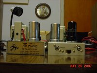
The OEM power trafo may be up to the job. Please look at the attached photo of a Fisher PR-6. The Allied 6K27VF is rated for 600 mA./6.3 VAC plus 15 mA. of "150" V. B+ and its dimensions H/W/D (in inches) are 2 x 2.375 x 1.75, which seems to be reasonably close to the OEM trafo's size.
The OEM trafo is spec'd for 130 Ohms primary DCR and 340 Ohms rectifier winding DCR. Due to the "standing" DC associated with 1/2 wave rectification, the winding has to be able to take some punishment.
The more I think about it, the more inclined I am to use the regulator and set the unloaded current at "5" mA. In the event of a power trafo failure, the 6K27VF is a very suitable replacement.
Let's see, CRC filter with 10 muF. (for a large conduction angle)/3.3 K Ohms, and 150 muF. Use 301 Ohms plus 27.4 KOhms in the regulator set pair and call the PSU finished.
Attachments
A bit late but what about the Supertex LR8N3?
Max V = 450V, Min Output Current for stability = 0.5 ma
http://www.supertex.com/pdf/datasheets/LR8.pdf
Up to 100 ma with TIP50 pass as here:
http://www.antiquewireless.org/otb/resto0504.htm
Max V = 450V, Min Output Current for stability = 0.5 ma
http://www.supertex.com/pdf/datasheets/LR8.pdf
Up to 100 ma with TIP50 pass as here:
http://www.antiquewireless.org/otb/resto0504.htm
I forgot about the LR8N. That's a good suggestion, drj759. I have extensively used a similar part, the now-obsolete Harris/Intersil HIP5600 (perhaps the same design sold to Supertex?). I regulated every stage, including the PP output stage, of my 7119-based headphone amp with them. I'm sure the LR8N could have dropped in as a replacement. I bought a "lifetime" supply of the HIP5600, but I still use the Maida/LM317 where I can because the output Z is lower and transient behavior is a bit more, ah, dignified.
Neither the LR8N nor the HIP5600 performs as well as a Maida/LM317, but the low minimum current of 0.5mA is the big factor for Eli's application.
Neither the LR8N nor the HIP5600 performs as well as a Maida/LM317, but the low minimum current of 0.5mA is the big factor for Eli's application.
drj759 said:A bit late but what about the Supertex LR8N3?
Max V = 450V, Min Output Current for stability = 0.5 ma
http://www.supertex.com/pdf/datasheets/LR8.pdf
Up to 100 ma with TIP50 pass as here:
http://www.antiquewireless.org/otb/resto0504.htm
Not late, at all. Parts have yet to be ordered.
THANK YOU!!The LR8 by itself is adequate for this low current situation.
For peace of mind, a "flag" heatsink will go on the TO92 case. We'll go back to a 1 mA. unloaded draw. The combined draw (< 2 mA.) should be a "piece of cake" for the OEM power trafo. The icing on the cake is that the prefered parts vendor of Mike (the owner of the "boxes") is Mouser. Hmmm, CRCRC filter using 10 muF./5 KOhms/33 muF./5 KOhms/100 muF. Put a 100 nF. film part immediately adjacent to the regulator IC to improve transient response. Things are looking GOOD.
BTW, the linked TIP50 augmented circuit looks interesting for higher draw situations, like power O/P screen grid supplies.
- Status
- This old topic is closed. If you want to reopen this topic, contact a moderator using the "Report Post" button.
- Home
- Amplifiers
- Tubes / Valves
- Maida Regulators Redux