I need a shunt regulator for my Aikido linestage.
My current PSU is a CLCRC. Ripple rejection is good...however, it is susceptible to both AC line variation and load current draw variation.
So, basically, I need to stabilize the macro B+ level. Additional ripple rejection is not a requirement here.
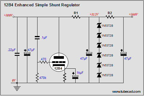
I've been looking at Broskie's Feedforward shunt regulators, and the one shown below:
Since I am still new to all of this, does this shunt regulator accomplish both of those objectives?
Also, how important is a PSU's output impedance in all of this?
My current PSU is a CLCRC. Ripple rejection is good...however, it is susceptible to both AC line variation and load current draw variation.
So, basically, I need to stabilize the macro B+ level. Additional ripple rejection is not a requirement here.
I've been looking at Broskie's Feedforward shunt regulators, and the one shown below:
Since I am still new to all of this, does this shunt regulator accomplish both of those objectives?
Also, how important is a PSU's output impedance in all of this?
With proper design, either shunt or series regs will do what you want.
Since the Aikido is run in Class A, why are you getting load current variations? If you actually are, the reg will certainly help, but you're more likely to kill the problem by taking another look at the CLCRCLRLCCRC or whatever and possibly (gasp) simplifying it. With a reasonably low ripple supply, the Aikido works very well- I haven't found any advantage to getting very fancy.
Since the Aikido is run in Class A, why are you getting load current variations? If you actually are, the reg will certainly help, but you're more likely to kill the problem by taking another look at the CLCRCLRLCCRC or whatever and possibly (gasp) simplifying it. With a reasonably low ripple supply, the Aikido works very well- I haven't found any advantage to getting very fancy.
The CLCRC psu I have is pretty simple:
Lundahl transformer
5ar4
3.3uF cap
15H 60R choke
120uF cap
1000R resistor x2 (one for each channel)
20uf cap x2 (one for each channel)
I removed the second stage LC and replace with an RC filter to remove a possible resonant filter.
After further investigation, I have found that my Aikdio linestage with all 6sn7s is actually pretty demanding on the PSU. If I increase the cap that sits on top of the voltage divider for the PSU noise induction section into the cathode follower stage to 10uF from .1uF, it reduces the LF noise I am seeing at the output.
However, that means I am injecting large voltage swings into the top and bottom of the tube, and that's not an ideal state.
Swapping out the 6sn7 for 6bx7's and 6as7's in the cathode follower stage results in even bigger LF noise on the outputs...
Again...leading me to believe it is a problem with voltage regulation on the B+ stage.
So...at this point, I see B+ regulation as my last step of investigation....
Actually, you'd expect the hum to go up if you put in tubes with different mus. I've found that the null for that resistive string is fairly sharp, so changing the mu even 10% will certainly change the output noise.
What values of resistors are you using in that string?
edit: By LF noise, do you mean hum or just slow perambulation? If the latter, how are your heaters set up?
What values of resistors are you using in that string?
edit: By LF noise, do you mean hum or just slow perambulation? If the latter, how are your heaters set up?
SY: The resistive string uses a 100k resistor on top and a 121k resistor on the bottom. (That is set up for 6SN7s, but it is close to the values for the 6BX7). For the 6AS7, I shorted the 100k resistor, as per Broskie's resistor value calculations.
The heaters are currently AC, biased up to 1/4 of the B+. I'll go get a lantern battery today, and swap that in to test DC heating.
And, yes, the LF noise is very low frequency perambulation. My speaker woofers wobble in-and-out occasionally.
The heaters are currently AC, biased up to 1/4 of the B+. I'll go get a lantern battery today, and swap that in to test DC heating.
And, yes, the LF noise is very low frequency perambulation. My speaker woofers wobble in-and-out occasionally.
OK, good work!
The size of the resistors in that string is pretty much what I expected- that's why changing the cap size had such an effect. In any case, if things are bouncing around so much, you can go directly to the finish line by substituting a couple of Maida regulators for the RC filters. If you want to experiment and probe a little more deeply, change the top resistor in the cancellation string to a higher value (say, 200k) and parallel it with a 250k-500k trimmer. Adjust it for the best noise null, then see what the actual value is. I've found that John's suggested values are a good starting point, but are not the final word.
The size of the resistors in that string is pretty much what I expected- that's why changing the cap size had such an effect. In any case, if things are bouncing around so much, you can go directly to the finish line by substituting a couple of Maida regulators for the RC filters. If you want to experiment and probe a little more deeply, change the top resistor in the cancellation string to a higher value (say, 200k) and parallel it with a 250k-500k trimmer. Adjust it for the best noise null, then see what the actual value is. I've found that John's suggested values are a good starting point, but are not the final word.
Two questions:
1) For the resistor string, since they just form a voltage divider, do the actual values matter, or just the ratio? Do I get a deeper cutoff frequency 100k/120k resistors instead of a 50k/60k resistor string?
2) For the Tubecad regulator shown above, how do I calculate the 3 resistors that are not specified (R1, R2, and the cathode resistor)? And what might be the current draw limit?
Thanks!
- Status
- This old topic is closed. If you want to reopen this topic, contact a moderator using the "Report Post" button.
- Home
- Amplifiers
- Tubes / Valves
- Shunt regulator question