Hi
So I did some reading and to my surprise, it would seem that I could convert my Marantz 8B to SET and/or bridge the input/output to make it a monoblock. Not that I'd ever do that but I do have an old PP EL84 amp that I would consider applying this idea to. Anyone try this? Bad idea?
The same EL84 amp also has 3 12AX7's per channel and more gain than I could ever need. Without having a schematic handy, what are the chances I could remove two of the three 12AX7's to simplify things? Can I simply remove the tubes or must I rearrange the circuit some? I assume the latter.
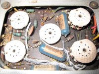
No such thing... yet. I've got to trace everything to put a schematic together. A lot of the guts are in the front panel. The best I've got so far is a couple photos
look for the Calbest:
http://mysite.verizon.net/oldamps/
look for the Calbest:
http://mysite.verizon.net/oldamps/
Hi Again, Looking at the photos, two things sort of jump out. One I would leave the Marantz alone. Vintage Marantz equipment is fairly good and nearly anything you might do would decrease its value. The newer amp though looks like it could be modified fairly easily. The circuit board seems to have been set up with the outputs and drivers on one side of a central dividing line. Everything else is on the opposite side. Sort of a modular arrangement. This is fairly common in equipment as a manufacturer can make several similar pieces of equipment on essentially the same boards. I would suspect that the output from the preamps (which from your post have too much gain) is by a single capacitor or jumper from one side of the divider to the other. They might also go to / thru the control panel. Cutting the circuit at that point and installing a volume control and perhaps a coupling capacitor might well be all that would be required to accomplish what you desire. If there is an existing volume control between the two parts of the circuit you could make the break there.
If some one else out there has thoughts on this I'd be curious. PS does the newer amp have any sort of label or designation. It might be possible to search the web for a circuit diagram.
Good listening
gofar99
If some one else out there has thoughts on this I'd be curious. PS does the newer amp have any sort of label or designation. It might be possible to search the web for a circuit diagram.
Good listening
gofar99
The same EL84 amp also has 3 12AX7's per channel and more gain than I could ever need. Without having a schematic handy, what are the chances I could remove two of the three 12AX7's to simplify things? Can I simply remove the tubes or must I rearrange the circuit some? I assume the latter.
I'm going to guess the 3 'X7s per channel are phono section, tone control, and driver/splitter.
The "iron" looks decent and that's a good sign.
Simplification is definitely possible, especially if the effing tone control circuitry goes away. Immodest proud papa that I am, I'll suggest you use the "El Cheapo" splitter/driver and keep PP EL84 "finals". PP 6V6s would be fine too. To use PP O/P trafos with SE circuitry requires parafeed topology, with the addition of heavy and costly plate loading chokes.

Closing the openings the PCBs go in with sheet Aluminum seems reasonably easy. Of course, you could design and etch replacement PCBs.
BTW, I don't think the "Calbest' is recent. It looks like there's a Sep., 1969 inspection date stamp on the chassis.
I most certainly won't fool around with the Marantz 8B, but it was given me to use and enjoy rather than to be a museum piece.
The Calbest is an ancient Japanese model sometimes branded as a Musicall. 1959 and rare, but surprisingly good sound when compared to a standard like the Marantz. I don't think I have any use for the phono stage in this amp, but the tone controls are important. There's also a lot of spaghetti inside that could be cleaned up.
I'm thinking it may be better to leave well enough alone and just focus on solving the weird zapping sound it makes. I'd sell it, but I'm afraid a replacement would cost 10 times as much!
Greetings, Apparently I got in late on part of the stream, Zapping?? When? A few things come to mind, but details would help. I also would keep the EL84 PP configuration. They are decent tubes and can work in triode, UL or pentode mode. I prefer the UL for a compromise in power and sound quality. I'm in the process of building a new amp with them and will post how it goes at a later date (the trannies haven't come yet).
If you need tone controls (I won't go into the arguments for or against) Lighthouse Electric on the web sells a low gain tube kit for about $60US that is fairly good. I used one for a while. The biggest problem with it was it needed real clean power and the bass and treb controls had to be kept away (or shielded) from A/C sources.
Good listening
gofar99
whitelabrat said:The Calbest... I don't think I have any use for the phono stage in this amp, but the tone controls are important. There's also a lot of spaghetti inside that could be cleaned up.
I had a Harmon Kardon A230 with a similar layout. Three small tubes per side, plus push-pull output EL84. One tube was for the phono pre-amp, one for the tone circuit, and the last was the AF amp / phase inverter.
I chopped out the phono and tone tubes, but found the plate voltage on the AF / PI tube started to creep up on me (265 volts or so, when it should have been 215). I don't know if it was enough to stress it, but I preferred to try to keep things close to spec. I put a dummy load (big resistor) where the missing tubes used to be, and everything seemed to fall back in line. I won't swear this is a good approach, but the amp seems to suffer no ill consequences.
I guess my point is that if you choose to eliminate tubes while you're cleaning out spaghetti, you might alter the operating voltages coming off the power supply.
I don't think I have any use for the phono stage in this amp, but the tone controls are important.
Your wish is my command.
I've attached a Max Robinson design. 2 'X7s per channel and a DC heater supply are a bit much for tone controls. However, the cathode follower triodes can be replaced by DC coupled ZVN0545A MOSFET source followers, as described in MOSFET Follies. Be certain to use Sovtek the 12AX7LPS (a true 7025 equivalent, with a hum bucking heater) in the tone control "holes", so AC heating is quiet.Make the signal processing circuitry totally defeatable. It should be in circuit only when absolutely necessary. Also, when in use, the tone control circuitry should insert between the source selector switch and the volume control circuitry.
Attachments
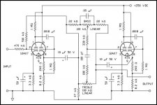
Greetings, That is a most interesting tone control circuit. Just out of curiosity, was it done in a PSpice variant or by trial and error. Just at a first glance it seems to have a number of intertwined feedback loops rather than the more common one or two local ones. I also wonder if the gain is sensitive to output loading. A neat design in any case.
Good listening
gofar99
Good listening
gofar99
To reply to gofar99 the zapping sound is a sort of hum that slowly increases in volume and then makes a sort of zap sound and disappears for a bit. It happens only on one of the channels. I noticed that it gets worse when holding my hand near the volume controls (center of front panel) or moreso when holding a screwdriver nearby the volume controls. I've replaced all the tubes except for the RCA 5U4GB rectifier so the issue is likely in the circuit somewhere.
The volume doesn't make a difference, so the problem is after the tone and phono circuits.
On different note the main thing I'm concerned with in pulling tubes out from the circuit is that the voltages will jump up. Thanks for the note on the Harmon-Kardon.
The volume doesn't make a difference, so the problem is after the tone and phono circuits.
On different note the main thing I'm concerned with in pulling tubes out from the circuit is that the voltages will jump up. Thanks for the note on the Harmon-Kardon.
Greetings, On the tube ratings a fairly good source of info is http://www.nj7p.org/Tube4.php. This is a tube database. A note about it is that sometimes you need to include the entire tube type like 6v6gt as it doesn't find it under 6v6. EL84s are generally maxed at about 300 volts. I usually run them a bit below that to help with longer tube life. 400 is probably a bit too much for any but the most robust variations. Pulling tubes from an amp might not be as bad as you think. If they are small signal or preamp tubes the drain on the B+ is often rather small, only a few milliamps per tube section. In any reasonably designed amp the power outputs will consume perhaps as much as 90 percent of the B+. If the B+ voltage jumps as much as I think you are saying (from 300 to 400) then something else is probably at work.
Regarding the zap. It sounds like a filter capacitor is charging up and then flashing over. I would start by checking the B+ filters, especially the first one after the rectifier. A second possibility is a bad bypass capacitor on the cathode of one of the tubes. A large value coupling capacitor between two high impedance stages can also behave in a similar fashion. My bet is on the first filter though, especially if the voltages are running above the design norms. I don't recall if you said if you measured the 400 with a tube rectifier or solid state ones in the circuit. SS ones will provide a higher voltage (less drop) than tubes and will charge up the circuit immediately. As the remaining tubes warm up (30-45 seconds usually) the voltage will usually drop. Hope this bable helps.
Good listening
gofar99
I reread your previous post, since the hum-zap is only on one channel. I would look for a filter cap on that channel first, then go to the cathode bypass and couplers. An unusual possibility is a "cold" solder joint that doesn't conduct until it hits a certain voltage. Sort of like the type of behavior that an avalance diode would do.
gofar99 said:Greetings, That is a most interesting tone control circuit. Just out of curiosity, was it done in a PSpice variant or by trial and error. Just at a first glance it seems to have a number of intertwined feedback loops rather than the more common one or two local ones. I also wonder if the gain is sensitive to output loading. A neat design in any case.
Good listening
gofar99
Unfortunately Max Robinson doesn't show that design any more on his FINE Fun With Tubes site.
IIRC, Max set the posted circuit up to be "unity" gain and have OK drive capability. I have no idea how Max came up with the circuit. Why not send the man an EMail?
Agreed. In the case of my HK, the B+ didn't move much at all when I yanked out the phono tubes. I was more concerned about the plate voltages on the driver stage. My power supply provides four sources. According to the factory (?) schematic, they are supposed to be 330V (B+), 300V (screens), 215V (AF/PI), and 160V (phono & tone). After I pulled the phono and tone tubes, I measured 325V, 309V, 266V and 262V. B+ and screen voltage looks OK to me, but I wasn't sure about the 266V.gofar99 said:Pulling tubes from an amp might not be as bad as you think. If they are small signal or preamp tubes the drain on the B+ is often rather small, only a few milliamps per tube section. In any reasonably designed amp the power outputs will consume perhaps as much as 90 percent of the B+. If the B+ voltage jumps as much as I think you are saying (from 300 to 400) then something else is probably at work.
After installing the dummy load, things settled down around 324V, 304V, 204V, and 142V. My dummy is probably pulling a little too much current, as the power supply is pulled a bit under spec. I used a 27K ohm, 5 watt wirewound resistor. Next time I'm in there, I'm going to add another 2.5K ohm in series.
So, the $100,000 question: does it bother a 12AX7 when you put 260V across it? The designer intended it to see 215. I figure in the best case, I moved the operating line to some place less optimal than what was in the original design.
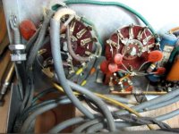
Those are relatively decent looking transformers on that Calbest. They don't seem to have UL taps on them, though. I see the blue and the brown wires going to the plates, but the screens seem to be fed directly from one of the power supply filter caps.
Hi, According to my RCA tube manual a 12AX7 has a design max plate voltage of 330. So your voltages should be OK. It is likely as you guessed that you are not in the best operating range. If you can determine what the plate load and cathode resistors are, I will check them against the design charts and see what if any changes make sense. Was the voltage you measured on the tube plate or on the B+ side of the load resistor?
Too bad on the transformers (no UL taps) It might be possible to run the outputs in triode mode. I believe you said you were using EL84s. If so and your outputs are actually running at 330 volts, then I would not recommend the triode mode. That voltage is already above the design max for the plates and feeding it to the screens would probably cause tube failure unless you are using one of the speciality type variants of the EL84 that can withstand more juice. Standard and NOS versions would not be suitable for this voltage. You also mentioned 6V6s, they would be ok at that voltage (up to 350). Triode mode would reduce your output power to about a third, but can have significant sonic benefits. It kind of depends on your speaker sensitivity, how loud you want the music to be and to a degree what type of music you like. If you like music loud with lots of bass and / or have low sensitivity speakers you can forget the triode mode. Changing to triode mode should you choose to go that route is often rather easy. Sometimes as simple as moving one connection per tube.
Good listening
gofar99
I would be interested in going pentode or perhaps wiring up a switch to go between the two possibilities.
I can't imagine the voltage is as high as 400V so it must be 300V. I'm going to test things and replace failing parts and then I'll recheck the voltage.
I believe I've figured which 12AX7 does what. I've got some close in photos for everyone to enjoy.
I need to double check, the the two sockets in the photo on the right are the EL84's
Attachments
To the right of the input, phono eq are the tone which stacks treble and bass (left) and volume which stacks left and right controls (right).
Anyone got any suggestion about what to use to replace the multi section ceramic cap on the tone control?
I should also mention that the controls are mirrored on the other side of the panel. They are all separate for each channel. There power, rumble filter, and eq curve switches at the bottom. Quite a lot of options for 1959!
Attachments
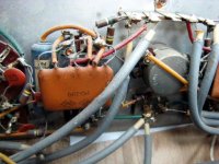
Hi, Oh wow! So much corrosion and it looks like there might even be some fungus attacking the wires. This could become a long term project. How easy would it be to remove the boards from the chasis? If there is someone out there with the knowledge of how to clean up the boards I believe help is in order. Feel free to jump in.
Let's try the easy question first. The cap stack. The first thing I do with them is look for numbers and logos. Then sometimes you get lucky with a google on them. Let me know what you can get off them. Second choice is to look at the other parts. Most tone controls follow standard circuit arrangements and by measuring the pots, and seeing what else is attached, a very good estimate can be made on the ones in the module. Then it is an easy job to replace the module with descrete parts. A third alternative is to replace everything with a standard bass/treb circuit. I can point you to several if that is what you want to do.
Overall, this looks like a worthwhile project, it just ain't going to be easy. Keep the faith.
Good listening
gofar99
- Status
- This old topic is closed. If you want to reopen this topic, contact a moderator using the "Report Post" button.
- Home
- Amplifiers
- Tubes / Valves
- EL84 mod questions