burnt Woodside STA35 valve amp... help
hey,
I have got a sta35 valve amp with one burnt sokket for el84 and one exploded chip. I want to fixs this amp and are desperat too find out what type of chip that should been there. are there anyone out there that know the name of this chip?? or have a schematics or a parts list or somthing?
I would be greatful for any help..
Tubes
While on the tube subject i found this = http://www.chambonino.com/construct/const3.html http://www.chambonino.com/construct/const10.html
While on the tube subject i found this = http://www.chambonino.com/construct/const3.html http://www.chambonino.com/construct/const10.html
Attachments
I believe (with the assistance of Google) that Woodside Electronics was formed after Arthur Radford retired in 1989.
The Woodside STA-35 is based on the Radford STA25 circuit but incorporated improved power transformer, power supply components and general component quality.
The Radford STA25 and STA25R diagrams can be found here: http://www.ampslab.com/vintage1.htm
Other info on of STA25 (without any chips):
http://www.walther-mathieu.de/PROJECTS/RADFORD/luckyfind.html
http://www.audio-muziek.nl/audio/audio-k1/kradfordsta.htm
Hope this may help.
(they are however EL34 / 6550, and not EL84)
Svein.
hi svein
thnx for the info..
this helped me alot..
i have already fixed the burnt out part..
and now i am waiting for som parts inclusive some new tubs/valves..
the problems in my ampmost likly started in the power supply. i found a defective tantalium condenser to the power (78l05) to the exploded part.
yes as you said the schematics of the radford sta-25r amp are very much the same with a few mods.
it looks like sta35 have sepert power supplys for its channel
In the power in the sta-25 there are a lm393 dual comparator op amp how ever in the sta-35 amp there are a bigger ic and this one are most likly a lm339 or simeler (correct me if i'm wrong) and are a quad comparator op amp.
also i noticed that in my amp there are different tubes then what the sta25 uses. my amp there are used ecc81 as input and a ecc82 as driver and el84 as output. ecc81 and 82 are dual triodes and from the schematics of the sta25 there are used an ecc88 as input (dual triode) and 6ua8 as driver (seems too be a pentode and a triode?) also kt88 or 6550 as output. anybody that knows why???
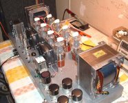
any way as said i have fixed one channel of the sta35 and it is working....")
it is working with one 12at7(ecc81), one ecc82 and two el84.. (if this is wrong plz let me know)
pictures are coming soon..
thnx for the info..
this helped me alot..
i have already fixed the burnt out part..
and now i am waiting for som parts inclusive some new tubs/valves..
the problems in my ampmost likly started in the power supply. i found a defective tantalium condenser to the power (78l05) to the exploded part.
yes as you said the schematics of the radford sta-25r amp are very much the same with a few mods.
it looks like sta35 have sepert power supplys for its channel
In the power in the sta-25 there are a lm393 dual comparator op amp how ever in the sta-35 amp there are a bigger ic and this one are most likly a lm339 or simeler (correct me if i'm wrong) and are a quad comparator op amp.
also i noticed that in my amp there are different tubes then what the sta25 uses. my amp there are used ecc81 as input and a ecc82 as driver and el84 as output. ecc81 and 82 are dual triodes and from the schematics of the sta25 there are used an ecc88 as input (dual triode) and 6ua8 as driver (seems too be a pentode and a triode?) also kt88 or 6550 as output. anybody that knows why???
any way as said i have fixed one channel of the sta35 and it is working....
it is working with one 12at7(ecc81), one ecc82 and two el84.. (if this is wrong plz let me know)
pictures are coming soon..
Thanks, could you please drop me a line? I have questions about the amp.
Many thanks in advance.
adz@fastwebnet.it
Many thanks in advance.
adz@fastwebnet.it
STA25R
An intersting sideline to this discussion is that, according to the schematic the STA25R does not have a filter choke in it's HT(B+)supply line. Elsewhere on this forum-in a section devoted to Chinese tube amps. I have expressed my opinion that L/C filtering is better than R/C smoothing, yet the STA25R(and the Yaquin MC100) have neither, whereas the original Radford STA25 did have a large filter choke in its B+ line.
I admit I have never seen, heard, or worked on the STA25R or MC100, so don't know what they sound like, though I'd imagine the former, at any rate is a great amplfier.
A further point is that I don't recall, in over 36 years of working with electronics, a Bridge rectifier circuit with resistors in series with each diode(STA25R cicuit is at <www.ampslab.com/SCHEMATICS/RadfordSTA25R.gif>) .
Finally, some people advocate using UF5408, UF4007, etc., instead of the normal 1N series, and I have, in fact done that in one amplifier PSU. Is this a good idea?
- Status
- This old topic is closed. If you want to reopen this topic, contact a moderator using the "Report Post" button.
- Home
- Amplifiers
- Tubes / Valves
- Burnt Woodside STA35 valve amp... Help!