Maybe bins too little. Here's what I got. Noise floor no test tone, response, 1kHz test tone.
edit: Now the correct files FFT
Hey Nick, did you make a note of what the preamp output voltage was for the last image?
First pic is loopback showing baseline at output level to measure 1W performance of amp. I have some 60hz niose, but it was do to crappy test rig.
As for 6V6, RCA blackplates is my choice as well. New Tungsol was very good( have matched quad for diff version), but Military grade RCA was worth money and this amp is worth the upgrade.
Its a beauty Mr Aldrin
LM317 works fine just adjust the current down until you get best performance.
I don´t remember exactly what i ended up with but it´s a bit lower then Salas original setup.
Depends on tubes brand and vintage also. CCSing for about 6.1V Vh is OK.
Hi
I made me a filament CSS and tried some different resistorvalues and I can confirm that tube brands/age etc varies a lot in the filaments, I get values between 5,6-6,4 volts just by testing a handfull.
Seems like I need a VR pot in parallel to adjust. Maybe 3,3/18/VR100 or something.
Whats the deal on going for current adjust and why not a voltage one?
It was impossible to tell since I still have this 100 Hz hum from hell that I dont seem to stumble over any solution to.
When I plug poweramp and pre in it starts with a gigantic hum that almost goes away when the 6V6es heats up and biases. But just almost.
The hum has some variations in character depending on how I feed the filaments. AC, DC, CSS, Voltage regulator, groundreferenced, lifted etc. But theres always a hum.
Maybe I'll throw the towel for now
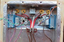
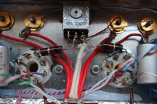
I grounded them from CSS zero to signal star ground. I found something else that is odd now. Right channel has a quite edgyer hum then left. In the right one I can also hear the wiper when moving. When I tap on the tubes I can only hear the tapping in the left speaker, mostly then I tap the left tube, but also when I tap the right tube (going through chassie probably). Needs som investigation of the audio circuit grounding, rca mounts etc. That one has been pretty much the same with all different PSUs and filament feedings.
- RCAs must be isolated from (any sort of ) chassis ; their GND must go to cathode GND return ...... usually main GND point
-1M from grid to gnd is must ; pot ( any sort of it ) is lousy grounder
-cathode GND return must be separate from grid GND return path ( meaning - separate wires to main GND point)
-local PSU decoupling must be as close to anode as possible ; if using shunt reg , reg itself must be close too - shunt regs don't like long wires , be it of high or low gain/feedback sort ( having error amp or no )
Last edited:
I must correct myself. Filament zeros was connected to PSU star. The audio star(s), one per channel is what you see on those pictures. Those connects at the PSU star wich is by the filter caps. That star then connects (or not connects, I have it so I can take it away since poweramp has a connection between audiozero and earthground) to chassie.
Maybe I need filament zero to connect to audio circuitry ground stars?
Maybe I need filament zero to connect to audio circuitry ground stars?
They are- RCAs must be isolated from (any sort of ) chassis
-
their GND must go to cathode GND return
They are
- ...... usually main GND point
Depends how you define main. I have one audio cirguit gnd points (on pics), thats because they are after SSHVs. Those connects separately to PSU star.
I'll put one--1M from grid to gnd is must ; pot ( any sort of it ) is lousy grounder
Grid leak is now tru pot so they are separate from Cathode gnd--cathode GND return must be separate from grid GND return path ( meaning - separate wires to main GND point)
--local PSU decoupling must be as close to anode as possible
Its hard when using SSHVs
Thanks guys, I'll have to run quick, brb in half an hour.
.
Depends how you define main. I have one audio cirguit gnd points (on pics), thats because they are after SSHVs. Those connects separately to PSU star.
sounds good - any point is good , if you declare it for main , and act accordingly
good praxis from yore , for connecting anode/cathode leads to iron - shield those wires going to choke and from it ;
from cathode to choke - ground shield on cathode side , other end leave open;
from choke to gnd - ground shield on choke side , other end leave open
put anode and cathode stoppers ditto on socket - ferrite beads preferably , if you don't have them 47 to 100R will do ( bigger on anode , smaller on cathode)
make voltage divider between +PSU and gnd , having app. 1mA through it .... with voltage potential some 40-50V above cathode ; put 10uF across lower resistor ; connect floating heater supply ( any end ) to that potential
if these steps don't help - post plenty of pictures ..... for now I have pretty Suede idea on what you are working , in fact
 ....... changing things all the time .....
......
Its hard when using SSHVs
.....

you can blame only your self for that ........ matter of physical layout ;
if you proceed in that direction , you must place some local decoupling near tubes ; say that anything more than 10cm of wires between shunt reg and tubes is critical , in my book ;
how you'll do with high S toob ? you would have fireworks
Last edited:
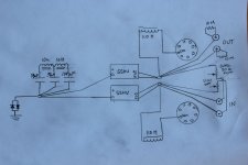
I'll contemplate and try to understand you, and ask questions when I have done. Heres a drawing I did on the grounding circuitry. It leaves out the gridleak which I will mount and aso the filament referencing, which Im contemplating where to connect. Comments on that?
Attachments
dunno for SSHV ground in/out topology ( Salas is da man for that ) but it seems to me that you must have separate diode blocks to chassis on both GND points on right side , deleting that existing one
you can't make half dual mono gadget , then make gnd loop with (usually) source having same gnd on both outputs ; that's same as little pregnant
if SSHV is having GND traces organization in perfect way , you are not having difference in potential between in and out GND and you can make it as shown
if case is different , each SSHV must have separate rectifier and filter
- Home
- Amplifiers
- Tubes / Valves
- 6V6 line preamp