Well, I started to interest in measuring now that you bossed me around on it a bit. Common mode chokes are good, with or without crappy measuring tools
But I think I have ruled out GND artifacts now, its the same results with yeallow/green GND in or out.
The thing that enoys me now is that my UNI-T (that say it shall measuere True RMS) follows the scope measurements anoyingly well but on some different scale. When I get 75 mV PP on Pico I get around the same RMS on the UNI-T
The DMM has 10MegOhm impedance, maybe that scope probe is another story. And mV in kHz are not a DMM's AC best sens.
If you want to know your DMM reports TRMS well put it on your Wavetek gen's output. Set the output at 1V range using sinewave. Then press square and triangle. It should show you x1.414 & 0.82 the previous RMS. Use 500HZ.
Yup. Need to invest in good probes, but otherwise works great. $100 on fleabay. Need to get a good sig gen, the PC can't put out clean HF square waves. Perhaps I am doing something wrong. Wrks great for distortion and that is what I got it for.
You do nothing wrong, the PC has a ringing problem with squarewaves. Get GW Instek 1013. 3MHZ DDS +/- 20ppm range stability per year level. Cheap.
FRom memory, it was pretty clean. First go round, I did my own boards. Only issue was drift of 170, i believe. Maybe due to heat, but I think you now suggest 117. I haev it sitting in closet waiting for two new Lundahl PSU chokes and more filtration. Trying to decide between single transformer and dual prereg feeding dual SSHV or dual allthe way. Got nice EI, but it is 230. NOt big deal to add outlet, as it seems like i nice one.


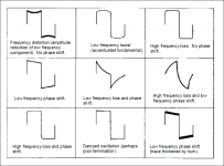
Cool. Lower left corner is a common one on my scoopings, but according to the pic the upper right one, rounded in all corners is better? Phase shift, what does that mean, what happens in the amp and why?
Btw I was at a friend last night and exchanged a bag of beer for one of his 5 scopes (or two actually) so now I possibly have something to relate the other measures to. Came home a bit late and a bit unsteady on hand so I skipped the HV fiddle.
Btw I was at a friend last night and exchanged a bag of beer for one of his 5 scopes (or two actually) so now I possibly have something to relate the other measures to. Came home a bit late and a bit unsteady on hand so I skipped the HV fiddle.
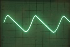
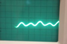
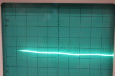
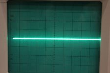
Well. I dont know if theres crap behind the buttons or behind the probes but this is what I could get out of the old Hameg 303-6 I borrowed.
First pic rectifiers (first C) 0,2 V/div 2 ms/div, second pic on second C 5 mV/div 5 ms/div third pic over dummy without SSHV 5mV/div 5 ms/div, fourth pic on SSHV dummy 5 mV/div 1 ms/div
First pic rectifiers (first C) 0,2 V/div 2 ms/div, second pic on second C 5 mV/div 5 ms/div third pic over dummy without SSHV 5mV/div 5 ms/div, fourth pic on SSHV dummy 5 mV/div 1 ms/div
Attachments
Last edited:
The Pico must read some noice from the diffprobe. I wonder if a thing like this could make it usable?
100MHz Oscilloscope High Voltage Clip Passive Probe, X100, Max. 2000VDC: Amazon.com: Industrial & Scientific
100MHz Oscilloscope High Voltage Clip Passive Probe, X100, Max. 2000VDC: Amazon.com: Industrial & Scientific
Buzz, look for a Leader LAG120B (pls note B), they are cheap and worth every penny. Discard LAG120A, not as good..... Need to get a good sig gen....
An example: Leader Lag 120 Audio Frequency Generator Test Stereo Amplifier | eBay
If you're lucky, you may also find a LAG126 or if you have some spare money, buy an Audio Tester 192A, same sig gen and a nice dual ch analogue RMS voltmeter with double needle for almost free
")
For those of you interested in testing your amplifiers, I built a version of this oscillator
Injection-lock a Wien-bridge oscillator | EDN
and got it to measure distortion of about 0.0006% (-104dB) at about 5V RMS output. Why this is significant? Because you will pay big $$ for a signal generator that has such output at such low distortion, but it'll cost very little to build the circuit in the above link. The problem with a sound card like the E-MU 0404 used to generate the signal is that as soon as you want a signal higher than about 300mV RMS you'll notice that the distortion of the generated signal is quite high.
In my opinion this little oscillator is good enough for testing tube gear. If people are interested I can post construction and parts choice details (which opamp, which light bulb, which buffer for output, etc.).
Well. I dont know if theres crap behind the buttons or behind the probes but this is what I could get out of the old Hameg 303-6 I borrowed.
First pic rectifiers (first C) 0,2 V/div 2 ms/div, second pic on second C 5 mV/div 5 ms/div third pic over dummy without SSHV 5mV/div 5 ms/div, fourth pic on SSHV dummy 5 mV/div 1 ms/div
All in order. Told ya it was a ghost.
- Home
- Amplifiers
- Tubes / Valves
- 6V6 line preamp