Good looks. Did you take any anti microphonic measures? Its the common cathode 15dB gain circuit yes?
My 6V6 preamp does'nt have much microphonic like my 71A preamp, so I have not to get anti microphonic treatment.
I increase grid stop Res to 3.3K, so noise is a bit lower
")
I don't understand much your mean about "common cathode 15dB gain circuit".
I mean the classic one 6V6 preamp that has gain, not the cathode follower buffer version a few make. If you swap your 6V6 bottles between channels does the hissier channel change? Is it you got one hissier tube or some difference in PSU, layout, that maybe creates one a noisier channel?
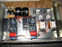
This one is making not that rigid a buffer, its nice as far as CFs go. And about 220 Ohm output impedance. Its a matter of synergy in a system also, blending tone. Anyway the gaining pre is the main theme here, CF is a spin off. Have you got any close up and inside pictures of the construction? People may like to see for ideas. Happy listening!
Anyway the gaining pre is the main theme here, CF is a spin off. Have you got any close up and inside pictures of the construction? People may like to see for ideas. Happy listening!
If you have pre with some gains, you can design power amp with only 1 stage of amplification. This preamp has almost 6V out.
Low output impedance is good. This preamp has nearly 1.5K, not bad so far
inside photo ? sorry, I did build this one for my friend and I sent to him
. But, I will draw the detailed schema as soon as possible.hi tcqanh, what's your view on this 6v6 pre connected via a step-down line optx? i need a low output impedance as my pre will be driving 2 power amps. don't like the CF approach as well
I don't like cathode follower buffer, I feel its sound become rigid, not more magic
hi tcqanh, what's your view on this 6v6 pre connected via a step-down line optx? i need a low output impedance as my pre will be driving 2 power amps. don't like the CF approach as well
Step down OPT is always good for output. But the problem is just its quality. Higher ratio is worse quality cause of parasite Capacitance and Fe material.
I like 5K- 600 ohms OPT for preampli, with this one you can make a preamp to many tubes that have internal resistance 1-2.5K. 6V6, 5687, 12BH7, 6C45P... are examples.
Note that how much DC max current can OPT get ? In my experience, you can take your opt run 1/2-2/3 max currrent. ex, opt can get max 20mA from data's manufacturer, you should run 10mA.
Last edited:
Just a quick update here. I whined over hum last time which was pretty childish of since I obviously cant build a proper PSU. I just putted something together that looks like any other preamp PSU i have done b4. I forgot to put in the fact that this pre takes more then 5 times more current that a normal one. As I had the scope up is measured almost 350 mV ripple on B+. The waves was exactly 20 ms (50 Hz) so there was not much to say. Unsufficient filtering.

So I got violent and squeezed in 2 old tube radio OPTs instead of the former 6K8 resistor.

Theyr about 11-12 H each on the primary and serves one channel each.

Ripple went down to around 2 mV which I can hear on my 99 dB speakers, but then I have to have ny ear in the cone. Otherwise I dared to play half a song and it rocked. I didnt want to shockride it to much since I had some 360 volts on the anodes.
So, there is hope.
And then I spoke to mr Per Lundahl today and he is more then happy to make me some http://www.lundahl.se/pdf/1667_68.pdf special gapped to 50 mA. I think a DCR of 680 is to prefer over my Hinchleys almost 1 k.
I will tweak on and listen some more before I decide.
cheers
Staffan
So I got violent and squeezed in 2 old tube radio OPTs instead of the former 6K8 resistor.
Theyr about 11-12 H each on the primary and serves one channel each.
Ripple went down to around 2 mV which I can hear on my 99 dB speakers, but then I have to have ny ear in the cone. Otherwise I dared to play half a song and it rocked. I didnt want to shockride it to much since I had some 360 volts on the anodes.
So, there is hope.
And then I spoke to mr Per Lundahl today and he is more then happy to make me some http://www.lundahl.se/pdf/1667_68.pdf special gapped to 50 mA. I think a DCR of 680 is to prefer over my Hinchleys almost 1 k.
I will tweak on and listen some more before I decide.
cheers
Staffan
Don't be so quick to blame it on the psu. 50Hz/60Hz hum can be the result of wiring or component location (near transformer) or transformer orientation. The grounding scheme makes a huge difference as well.
Your right Iko. I was refering to that I thought it was oscillation between the chokes and the output caps, wich would have been more irritating.
The measure above is from spagetti cabling, everything unshielded and with iron tweaked in here and there as you see. I can clearly just get better with some proper layout work.
best regards
Staffan
Oh, sorry. The triode curves. B+, current, kathode to grid voltage.
I know I could look back on the various scematics, I guess it was the reasoning behind it I was after. What operating points do you prefer?
Choke loaded CF points or resistor loaded? In choke loaded case I need to know the inductance and resistance of your chokes.
- Home
- Amplifiers
- Tubes / Valves
- 6V6 line preamp