I wouldn't use LM317 for 1.6A. 1.5A is its datasheet max on a good sink.
Since the load is reasonably constant, you can use the trick of having a resistor bypassing the regulator, sized to pass 1A or so. The regulator cleans up the last 0.5A, allowing a 317 and a smaller heatsink.
Salas,
Are you saying 40uF for first stage. In your. drawing there is 470uF. I can easily combine resistors and make into 160R to 4.7uF(i have1 uF or 2) to choke to 40uF.
Triode Al,
570R wouldgive way too much Vdrop and i would not have enough for regulator. Are you saying standard EI trafos have higher internal resistance and help in ths regard? Also, i do not have CT, although numerous schematics have shown non CT configuration, although it makes senses about signal not being balanced. I had planned to wrap toroid with another winding as suggested by KevinK, i guess i could do two and make sure they are balanced.
4 muF first stage is what specs say! But at lower voltage you might cheat a bit, but not as high as 40 muF
Indeed 575 ohms is too much (for max voltage) but at least 200 ohms is reasonable.
As I measured several times EI have a higher internal resistance. It is easy to add a balanced 2.5+2.5 AC winding (12 turns each at 0.2 V/w?). The way I do it is make them bifilar first (say 12*12 cm)x2 slightly wound around each other .
What ga wire are you figuring om and is standard chassis wire acceptable or do i need something different?
Since the load is reasonably constant, you can use the trick of having a resistor bypassing the regulator, sized to pass 1A or so. The regulator cleans up the last 0.5A, allowing a 317 and a smaller heatsink.
Sounds like a great option as I have several LM317's on hand. Trying to source some decent power transformers. Doesn't seem to be a lot of options for the higher current required. Would a 12V transformer have to much extra voltage to drop?
Last edited by a moderator:
Sy,
Thanks for that! Great specs (they'll fit in my 2"H chassis I have on hand). I'll pick up something a bit smaller for the 3 12AT7's in the driver board and I'll be set. I'll let you guys know how it turns out. I'm a firm believer in regulation after hearing Salas' pre-amp.
Thanks for that! Great specs (they'll fit in my 2"H chassis I have on hand). I'll pick up something a bit smaller for the 3 12AT7's in the driver board and I'll be set. I'll let you guys know how it turns out. I'm a firm believer in regulation after hearing Salas' pre-amp.
Changed filter layout and sibilance is gone, but hum is worse. I could try winding CT 5V secondary, but I remebered others talking about using a pot to trim out imbalance and found this
The Valve Wizard
I have the resistors and also 500R pot, It would seem the resistors are more precise in matching but pot gives more leeway, Any suggestions as to better route.
BTW, DemonKleaner,
I don't want to put words in his mouth, but i think Sy may have been asserting that because the filament current draw is pretty steady, you don't need as much headroom for the regulator to be able to maintain current level that is set. Very different scenario from using a as a PSU for a dynamic circuit like an amp where there are constant fluctuations in draw.
Last edited:
Tried the dual resistor trick in above example and it was a no go. Something is not right. I am wondering if i need to increase resistor value. THe dual 100R resistor seemed to sink all the current from the tube. I connected ground point to first node of filter, should I have taken int to common ground?
I need some help with this. I tried the two resistors tied on one end to each filament and other end tied together on to ground point at first cap. It not only didnt work, it caused smoke. This makes no sense to me except for a reference somewhere about not tying the ground point of dual resitor setup to cap due to spikes in voltage. also saw where some put a cap between dual resistors and ground. What am i doing wrong here. I have a 1K pot to try humdinger, maybe 500ohm, but i cannot find any diagram that shows something different than what I have done. I really want to listen to this thing, because i can tell it has changed, even with the hum.
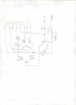
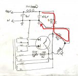
Those 100R would drop all the heater voltage and get smoking. They could be located at each plate in series with the 330V taps instead of having a single 165R for damping maybe.
100R+100R in non center tapped heater secondaries they use between them not in series, to ground reference or voltage lift AC heated signal tubes.
100R+100R in non center tapped heater secondaries they use between them not in series, to ground reference or voltage lift AC heated signal tubes.
Those 100R would drop all the heater voltage and get smoking. They could be located at each plate in series with the 330V taps instead of having a single 165R for damping maybe.
100R+100R in non center tapped heater secondaries they use between them not in series, to ground reference or voltage lift AC heated signal tubes.
are you saying that the 100R should not be connected to each other. Could you draw a pic. This is not making sense as everything I have seen shows this kind of setup, but clearly I am missing something. IT would seem that having the two resistors tied together would indeed make a series connection were one should not be, bypassing the internal connection of the heater.
For instance, the link i posted earlier,
The Valve Wizard
what am I missing here?. I know its me, but i dont get it.
FWIW, my star ground point is chassis, with single wire going to earth. I have not lifted starground, but everything I have read seems to suggest this is ok for PSU.
Last edited:

- Home
- Amplifiers
- Tubes / Valves
- 6V6 line preamp