I can hear music from my preamp with no speakers. This is awesome.....or terrible
Great if it was a turntable.

I can hear music from my preamp with no speakers. This is awesome.....or terrible
New concept, OSL, Output Speaker Less
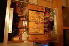
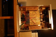
Here ya go. My next guess is grounding scheme. I have each PSU connected to earth seperately and all signal grounds, plus filament ground starred at regulator output.
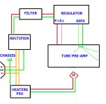
Try a simple one like this first. Connect signal grounds also to the shown pre-amp star.
*Do I see the plate load resistor directly on +force and then the +sense wire going elsewhere in your pic? It will not do. 2 wire pairs go to 2 defined B+ and GND points. No more on the regulator outputs is allowed.
Attachments
Mine is connected this way with the exceptionthat filament ground is attached to sense. I will route it to psu grounds like your pic. Sense wires are both connected to same place as force. Signal grounds are connected as you have them drawn. I will rework signal wiring before work.
Thats where one screw up is. I have B+ connected above Rl and S+ connected below Rl. Found it while rerouting grounds. Unfortunnately i zapped a filament this morning, so i will have to get some more tubes. Lets hope the one channel works. I am changing my avatar to Muddy Waters.... because thats what i do to a thread.
Bingo! Sense transistor was stealing my signal. I have to readjust B+ and install new tubes and we should be ready to go.Thank you for entertaining a fool for so long. Ight as well get a tube rectifier while i am at it. Can i put all the pre filter with seperate psu enclosure. I noticed Gregpry did this. Got shielded AC cable bringimg in both rails currently. Could put small decoupling cap in main box.
I suggest you bring it to ''full play'' status as it is first, 100% nice with no ground loops etc. Evaluate for a while, then you take next steps. Of course you can change arrangement or substitute rectifier, but evolve a good grasp of its practical routing and sound signature first.
I suggest you bring it to ''full play'' status as it is first, 100% nice with no ground loops etc. Evaluate for a while, then you take next steps. Of course you can change arrangement or substitute rectifier, but evolve a good grasp of its practical routing and sound signature first.
Excellent advice. Just excited to get it running. I like things to be tidy, so i immediately started thinking about ways to "clean it up". PRefilter outside of the box would help a lot. Oh well. In time. Thanks Salas.
I understand you want to finish it optimally all in one go but a P2P tube preamplifier with specialized regulators and CCS for heaters, two channels in a box and all that routing, can bring too much new data in one go for a first attempt by a class A Mosfet background guy. So far much is done in not too much magic smoke. Take a breath.
- Home
- Amplifiers
- Tubes / Valves
- 6V6 line preamp