Nice, thanks. Effective solutions for box space and cost. Congratulations for finishing it. Those green Russian output capacitors were marrying happily with FT-3 0.1uF Russian Teflon bypass in some older experiments I did, maybe you can try if you got any. I should see to run a spice sim about the 6L6GC & TL431 schematic if I can get the models. Is the heater reg voltage source or current source?
What amp and speakers you drive with this preamp? What you had before in its place?
I have FT-3 0.22uF, will try later.
Regarding the shunt reg sim, I would like to know, thanks.
The heater reg is a simple 7812 reg, current source worth to try?
I have a Matisse Fantasy clone, difference is thicker mid but a bit rough sounding comparatively to the 6V6 line amp.
Power amp is Aragon Palladium, and speaker is ATC SCM 50P.
Let us know what happened with those FT-3.
It got a bit more flowing with the 317 as Isource like in page 81 schematic, 2x. Will take about a minute to come up. Slow heat up. Can be good for NOS 6V6 long life though. Talking about tubes those are distinguishable in such a circuit. What make are those smoked glass ones in your photo? Exchange some brands if you have around or can lend from friends to taste.
It got a bit more flowing with the 317 as Isource like in page 81 schematic, 2x. Will take about a minute to come up. Slow heat up. Can be good for NOS 6V6 long life though. Talking about tubes those are distinguishable in such a circuit. What make are those smoked glass ones in your photo? Exchange some brands if you have around or can lend from friends to taste.
Hi Salas, a good recommendation to parallel with FT-3, the mid came through with the smooth delicate high, overall a more balance presentation, I love it.
Will change to current when I have time.
Those smoke bottles are Sylvania, have another 2 pairs, Hytrel & GM Genuine Parts, the GM sound quite similar to Sylvania, rebrand maybe?
Just for the record, I used 2 point grounding like Sakuma. Absolutely no audible hum, at least in my system.
Will change to current when I have time.
Those smoke bottles are Sylvania, have another 2 pairs, Hytrel & GM Genuine Parts, the GM sound quite similar to Sylvania, rebrand maybe?
Just for the record, I used 2 point grounding like Sakuma. Absolutely no audible hum, at least in my system.
Quick question -
I have a transformer that has a 6.3v 2A filament winding, and it also has a 5v 2A filament winding.
The B+ winding is only 540v CT so there isn't enough extra to use a tube rectifier.
My question is this - is there any problem making both of the fil windings go into a voltage doubler and then their own regulator, each lighting one 6V6? I.E., using the two windings to heat two tubes? (because one winding by itself cant do both...)
It seems like an efficient use of the transformer.
Sakuma was talking the same thing as American engineers call bus bar grounding?
Not too sure, but what I did was tie all signal ground + heater ground together, connect to chassis near input point, psu ground to chassis at one of the transformer mounting screw. It's quiet.
Quick question -
I have a transformer that has a 6.3v 2A filament winding, and it also has a 5v 2A filament winding.
The B+ winding is only 540v CT so there isn't enough extra to use a tube rectifier.
My question is this - is there any problem making both of the fil windings go into a voltage doubler and then their own regulator, each lighting one 6V6? I.E., using the two windings to heat two tubes? (because one winding by itself cant do both...)
It seems like an efficient use of the transformer.
No problem, bit better isolation even. Its the same for the original in post #81. The 6V6s are just 0.45A Ih each though.
What is your B+ PSU DC right after the rectifier diodes across the first smoothing capacitor? Also using a 7812 for heaters means you strung them in series?
395VDC,
Yes, 7812 series reg, heater of 6V6 in series, about 5.8-5.9 across each tube heater.
B+ is 292V, 18mA through the circuit.
Thanks Salas!
Regarding the shunt reg sim, I would like to know, thanks.
395VDC,
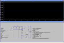
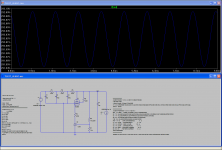
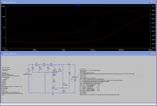
Based on your schematic and data I constructed a sim. Things of notice are:
1. Substantial voltage has to be be dropped across some series ballast to protect the tube cascoded chip for max current. As you did with your RC cells.
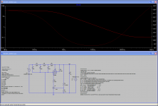
2. Ripple eating is so so but it works. Fed 2Vpp 100Hz dc source ripple and 10mApp 1kHz load play in the sim. 140-180mVpp on output. 12.5 times rejection on average (22dB).
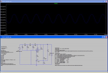
3. The output capacitor looks better placed across the high value resistor and trimmer leg for filtering the TL431 ref node. Its a noisy enough chip by itself and that resistor combo is big for Johnson noise. Don't know about stability in that case, it takes much more elaborate modeling and feedback nodes breakage of some full TL431 sub circuit. A practical test would tell much faster. Zo goes higher the opposite way for cap full output shunt or resistor leg shunt, has to do with its bootstrapping the ref or not also. Thus it eats 100Hz ripple stronger due to AC feedback (pic3).
Attachments
No problem, bit better isolation even. Its the same for the original in post #81. The 6V6s are just 0.45A Ih each though.
Good, I didn't think there would be an issue, but it's always good to ask.
Yes, the heaters are only .45A, but the voltage doubler is a current thief, according to Broskie, you only get a bit more than 25% of the winding's AC current rating. (AC current/3.8 = DC current)
Hi Salas,
Thanks for the update, as it is, didn't hear any instability. Have been using for a week now, seems ok, did change the 10uF across to the resistor and TL431 ref point this morning though, still run as good.
Thanks again.
Keep it coming if there is any more recommendations.
Thanks for the update, as it is, didn't hear any instability. Have been using for a week now, seems ok, did change the 10uF across to the resistor and TL431 ref point this morning though, still run as good.
Thanks again.
Keep it coming if there is any more recommendations.

- Home
- Amplifiers
- Tubes / Valves
- 6V6 line preamp