Again, thanks for the speedy response!
Has anybody tried the SSHV2 in this circuit? It's interesting. Or should I just stick with the Madia? Also, what about the big, dumb approach? CLC with lots of H and uf?
Do whatever is easier for you faster. If you will hear any anode born buzz then you need a reg. Maida will clean the scene from ripple buzzes, SSHV1 was smoother than a Maida and SSHV2 is even more resolute than SSHV1 but no harsher, so start easy, you see for yourself if you initially care for the 6V6 tone in the rough, and you plan from there.
That is, of course, very good advice!
I am actually hoping to use this as an excuse to try a Shunt Reg...")
That said, I'm sure I will try it with a unregulated supply first.
Oh, another question which I forgot to ask earlier, has anybody tried an active cathode load? Some sort of CCS, or a couple of diodes, or batteries?
I am actually hoping to use this as an excuse to try a Shunt Reg...
That said, I'm sure I will try it with a unregulated supply first.
Oh, another question which I forgot to ask earlier, has anybody tried an active cathode load? Some sort of CCS, or a couple of diodes, or batteries?
About 215 or 220V from plate to ground I think, but its installed now can't open it for just a quick confirm.
You are altering the bias point with such changes you realize.
Um... Time for a noob question...
If the voltage on the plate (via a lower B+ and a smaller resistor) is the same as in your design, I.E., 200v, how is that changing the bias?
Isn't the bias and load set by V Anode to Gnd and V plate? Or is where something else?
There must be something I dont understand... my knowledge in this area is low.
As I was looking through my junk box I found some things that I had completely forgotten about; a transformer of the proper voltage and a Welborne Labs PS3 regulator. From a failed project long ago. I hooked them up and everything seems to be working well, with a B+ of 327v. I'm fairly sure that I can adjust that to the specified 340v with the change of a few zener diodes. But as it's only 13v off, a paltry few percent, I'm sure it will be fine for the time being.
Concerning the screen resistor, the closest thing in my was 150ohm, is that going to be a problem?
Also, in regards to the cathode bypass cap, I've nothing close to 1000uf. I can parallel a few to get 440uf, or go much bigger, 2200uf. I have no knowledge which way to err... bigger or smaller?
Now I just need to klugde up some plate resistors. I think I can get close to 5K with the required dissipation.
Salas, yes, I will play around with the tone of the bypass cap. At the minimum I plan to have a film bypass of some sort.
On my next Mouser order I will get the 1000uf Silmic caps.
Some quick photos of the breadboard being built -
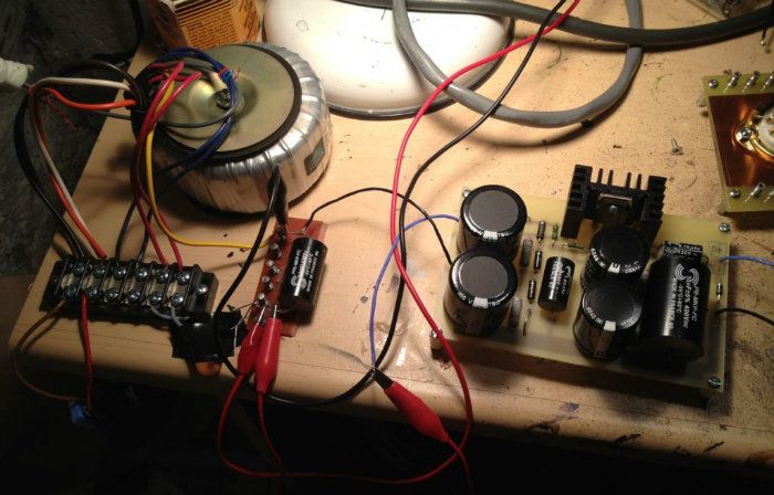
The PSU. Rectification is currently being unglamorously handled by a pair of 1N4007's. The old PS3 module is nice, and after looking at the manual, I can change the set voltage with a change in the zener string. Also, there are a few chokes in the parts collection that might be ideal for a pre-filter. I haven't measured the noise and ripple yet.
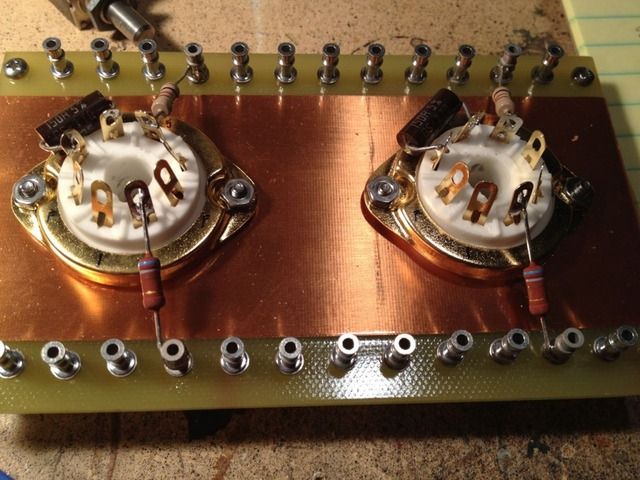
This turret board was bought long ago for a project that never made it past the breadboard, and has been looking for a home ever since. It's perfect! I will soft-mount it below the main chassis.
On my next Mouser order I will get the 1000uf Silmic caps.
Some quick photos of the breadboard being built -
The PSU. Rectification is currently being unglamorously handled by a pair of 1N4007's. The old PS3 module is nice, and after looking at the manual, I can change the set voltage with a change in the zener string. Also, there are a few chokes in the parts collection that might be ideal for a pre-filter. I haven't measured the noise and ripple yet.
This turret board was bought long ago for a project that never made it past the breadboard, and has been looking for a home ever since. It's perfect! I will soft-mount it below the main chassis.
The (basic) schematic of the regulator.
An externally hosted image should be here but it was not working when we last tested it.
The (basic) schematic of the regulator.
An externally hosted image should be here but it was not working when we last tested it.
Salas, yes, I will play around with the tone of the bypass cap. At the minimum I plan to have a film bypass of some sort.
It does not look like a full reg, more like a current boosted voltage reference. Q1 in series should be strong enough for 40mA total bias 2 channels. What Mosfet type is it? What are the values of R2,C2? If you will have no cap across Rk you are introducing full band cathode degeneration, i.e. local feedback. With a small film you introduce it just in low freq. So normalize the SPL on pink noise with a slowly integrating meter like the Radioshack one if you are to compare with an electrolytic there, without is gonna be less gain and different THD. Nice turret board btw. This config you got is flexible enough to decide how you like it or not.
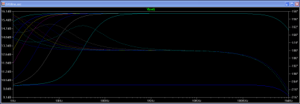
P.S. See what happens to freq. resp. and phase for 0uF 1uF 10uF 47uF 100uF 220uF 330uF 470uF 1000uF Ck values. 1000uF is light blue to graph's left and the rest are as we go down lower the values list moving to graph's right. 10dB bottom blue line is no Ck.
Attachments
It does not look like a full reg, more like a current boosted voltage reference. Q1 in series should be strong enough for 40mA total bias 2 channels. What Mosfet type is it? What are the values of R2,C2?
It's in my workroom which is accessed through my (sleeping) toddler's bedroom. I will report back tomorrow.
Also, that's not the exact schematic, but close. It's an older version of the same idea. I'm not dropping too many volts so dissipation should be fine, it's a big transistor. I have bigger heatsink if necessary.
If I can find the exact schematic will post it.
It's worth mentioning that one can replace the first R with a choke, I am going to try that tomorrow. The reg circuit would have even less ripple to control with a choke instead of a resistor, yes?
If you will have no cap across Rk you are introducing full band cathode degeneration, i.e. local feedback. With a small film you introduce it just in low freq.
So do you mean that a small film in parallel with the 1000uf is bad or does something different? I didn't mean to say that I was only going to use the small cap with no electrolytic.
So normalize the SPL on pink noise with a slowly integrating meter like the Radioshack one if you are to compare with an electrolytic there, without is gonna be less gain and different THD.
Ok, you lost me.
Nice turret board btw. This config you got is flexible enough to decide how you like it or not.
Yes, it's very nice. They are available from Antique Electronic Supply, and (unfortunately) are quite expensive these days. There are many configurations.
P.S. See what happens to freq. resp. and phase for 0uF 1uF 10uF 47uF 100uF 220uF 330uF 470uF 1000uF Ck values. 1000uF is light blue to graph's left and the rest are as we go down lower the values list moving to graph's right. 10dB bottom blue line is no Ck.
Ok, I understand what the different values do now in this circuit. It also looks that 470uf will be 'close enough' to the 1000uf that it will get me going without it being too different. Yes?
-I don't mean its not gonna have good enough voltage, it will not dynamically maintain it is the difference to a real reg, but don't bother its just a remark on the schematic's taxonomy. if its recommended to exchange a specific R with an L by Welborne then try it and compare, why not.
-Clarifying it was about simply bypass, ignore the very small values graph lines then, still see the value progression phase lines, how it turns down low. That is nice to keep in mind when auditioning this or that brand cap when the values are adequate but not the same.
-If gain is different between any circuits or there is bass region energy extension difference we should normalize the SPL with care to they surely sound exactly as loud for proper AB comparisons is what I was talking about.
-Maybe any less expensive alike turret boards on ePay? Its worth looking around for such stuff when building with da tubez.
Ok, I understand what the different values do now in this circuit. It also looks that 470uf will be 'close enough' to the 1000uf that it will get me going without it being too different. Yes?
Correct.
-I don't mean its not gonna have good enough voltage, it will not dynamically maintain it is the difference to a real reg, but don't bother its just a remark on the schematic's taxonomy. if its recommended to exchange a specific R with an L by Welborne then try it and compare, why not.
Yes, it is not a real regulator, more of a capacitance multiplier and voltage reference. Sorta. Anyway, it should help make the PSU quiet, if all works properly...
I mainly want to use it, just to use it! It's been sitting in a box for about a decade. After looking at the (current version) schematic on the Welborne website it actually isn't substituting a choke for one of the resistors... It's showing a CL before the regulator. Which is quite easy to implement, so it will be tried.
That is nice to keep in mind when auditioning this or that brand cap when the values are adequate but not the same.
And that is a very good point that might be missed by some people.
-If gain is different between any circuits or there is bass region energy extension difference we should normalize the SPL with care to they surely sound exactly as loud for proper AB comparisons is what I was talking about.
Ah, yes, I understand. I thought you were talking about something electrical in the bias circuit, not the overall gain due to the bypass.
-Maybe any less expensive alike turret boards on ePay? Its worth looking around for such stuff when building with da tubez.
Yes, it's certainly worth looking.
But I have this one already.
- B+ 13v off, a paltry few percent, I'm sure it will be fine for the time being.
- the screen resistor, the closest thing in my was 150ohm, is that going to be a problem?
- the cathode bypass cap, I've nothing close to 1000uf. I can parallel a few to get 440uf, or go much bigger, 2200uf.
- A slight deviation off an abstracted and averaged anode voltage is OK, every tube might be different anyway; don't worry and as you test it it will test good
- The screen resistor acts as a damper and 150 ohm damps OK
- On my R120 project I have used 68 uF (solid tantal, mil grade, good on HF) on my cathodes and it works well, with a -3dB of about 4-5 Hz. Good enough.
I have been messing with the circuit today and have learned a few things -
I have got some hummm, but I think it's a wiring problem. It goes away when the pot is turned all the way up or down, and worst at the mid-position.
I think I also have some filament hum, as they are AC for now. I will put together a quick and dirty regulator for them tomorrow.
I didn't write down any notes (which is stupid) but from memory the B+ is 310v under load, the anode has 200v, and the cathode 13v
The regulator schematic, for those who are interested -
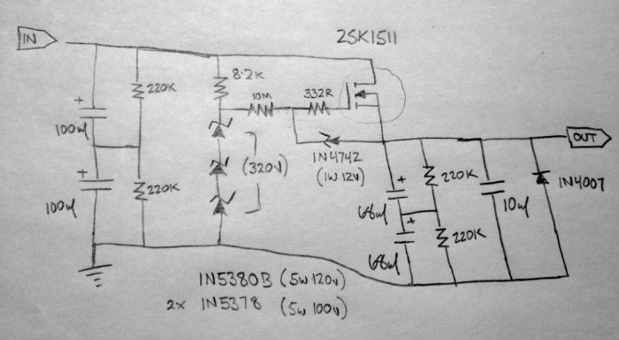
The zener stack controls the output voltage, so I can increase the regulated output by changing the zener string and tweaking the 8.2K resistor.
The power transformer I'm using is a bit too low voltage to get the full 320v. I will change it for another, that should make a difference.
I also want to experiment with an unregulated supply, CLCLC, I have a pair of 15H chokes.
I have got some hummm, but I think it's a wiring problem. It goes away when the pot is turned all the way up or down, and worst at the mid-position.
I think I also have some filament hum, as they are AC for now. I will put together a quick and dirty regulator for them tomorrow.
I didn't write down any notes (which is stupid) but from memory the B+ is 310v under load, the anode has 200v, and the cathode 13v
The regulator schematic, for those who are interested -
The zener stack controls the output voltage, so I can increase the regulated output by changing the zener string and tweaking the 8.2K resistor.
The power transformer I'm using is a bit too low voltage to get the full 320v. I will change it for another, that should make a difference.
I also want to experiment with an unregulated supply, CLCLC, I have a pair of 15H chokes.
- Home
- Amplifiers
- Tubes / Valves
- 6V6 line preamp