In principle, your mods shouldn't affect the stability. The layout is somewhat "aerated", but this shouldn't matter too much either. The most obvious possible issue is the distance from the board input to the filter cap: in principle, it is a supply regulator, meaning it is supposed to be very close to the main filter cap, but it seems you have a significant length of wiring separating the input from the low-impedance source.
If the wiring is unavoidable, you should place a capacitor directly on the board: the value or technology is not very important, provided it is 1µF or greater.
What type of MOSfet did you use? If it has significantly different capacitances, it could change the behaviour
If the wiring is unavoidable, you should place a capacitor directly on the board: the value or technology is not very important, provided it is 1µF or greater.
What type of MOSfet did you use? If it has significantly different capacitances, it could change the behaviour
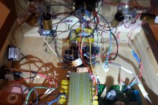
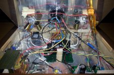
As the crow flies the board was 5-6 cm away from the L-C filter.
Due to the container used, apart from the two PSU boards, I connected with point-to-point wiring overall.
The SSR board was placed about in the right side of the power transformer, now I replaced it with the Maida and it work OK.
The mosfet is IRF840.
Due to the container used, apart from the two PSU boards, I connected with point-to-point wiring overall.
The SSR board was placed about in the right side of the power transformer, now I replaced it with the Maida and it work OK.
The mosfet is IRF840.
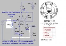
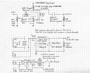
hiYes, sorry of course there are miriad of post here.... These are the schematics I followed:
The best pre-amps or tube line amps use cathode follower .
It is OK, it has already been used.The mosfet is IRF840.
The input wiring length/loop area could be the problem
Actually once resolved the issue of the board replacing it, another one came up then, which maybe was hidden by the previous hiss.
It's the presence of a hum that increases turning the potentiometer (of the amp). As for the preamp, on the other hand, the hum is maximum at the midpoint of the pot, to then be heard alternately a little to the right and a little to the left (on the headphones it seems more weakened in positions min and max).
I didn't check it with the scope yet.
Anyway I already faced off this thing in the past but now I don't remember how I fixed it.
A priori I wouldtend to exclude magnetic coupling because the noise doesn't stop moving away the toroidal transformer (it's for filaments). And the other P.T. transformer is oriented perpendicularly to the tubes...
Attachments
Midpoint is where a volume pot's max output impedance happens. When there is magnetic field coupling the higher the impedance of an exposed loop area the better of a hum antenna it becomes. Helpful can be coax signal cable and copper tape for wooden chassis dressing and grounding, also to wrap it as belly band (flux shield) on the transformers.
Sorry for suggesting something without experience in your circuit, but a gatestopper resistor could be tried in close proximity to maybe tame the MOSFET if unhappy in his implementation? 470 Ohm for example.It is OK, it has already been used.
The input wiring length/loop area could be the problem
There's also a cathode follower version of the 6V6 preamp. Link in post#1.hi
The best pre-amps or tube line amps use cathode follower .
Thanks Salas, I can try first with a coaxial cable as you say.
Now I remember that I already used the Sommercable goblin in another hybrid amplifier and it worked to bury the residual hum (linking the copper shield at top end to the main ground). I'll see if this can helps, then I think to the other solutions you suggested.
I have to say though that metal covering all the inner part of the box (it's a heavy oak-tree made) may be not so easy for me...maybe more feasible add the adhesive copper strips to the transformer.
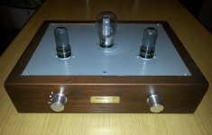
Here is the completed preamp and I'd like to share some pictures of it.
It wasn't an easy job for me this time, also because it doesn't have an underlying opening and it was more difficult to operate only from above with all the wirings...
The chassis is made from oak wood (hence the nameplate I chose due to the given final tint) and it's pretty heavy.
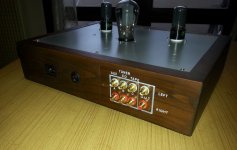
Following the previous suggestions I proceeded to change the cable to the 6V6 grid in favor of a shielded cable, while the wiring to the rotary switch is a twisted pair for each input (altogether three). Then I covered the bottom with aluminum adhesive tape, and the EI transformer with adhesive copper.
The only flaw is the housing of the two transformers inside which I had to orient to minimize the magnetic coupling.
For the rest, the device seems to bring pleasant sound notes, but I have to do more listenings to express me better about it...
It wasn't an easy job for me this time, also because it doesn't have an underlying opening and it was more difficult to operate only from above with all the wirings...
The chassis is made from oak wood (hence the nameplate I chose due to the given final tint) and it's pretty heavy.
Following the previous suggestions I proceeded to change the cable to the 6V6 grid in favor of a shielded cable, while the wiring to the rotary switch is a twisted pair for each input (altogether three). Then I covered the bottom with aluminum adhesive tape, and the EI transformer with adhesive copper.
The only flaw is the housing of the two transformers inside which I had to orient to minimize the magnetic coupling.
For the rest, the device seems to bring pleasant sound notes, but I have to do more listenings to express me better about it...
Attachments

Thank you Salas and Merlin!
Yes, perhaps I should cover the interior walls even further, maybe I will do it little by little by removing some individual parts attached there... Of course yes, I will put the Al tape linked to ground at the end.
The schematic used is this, Merlin...
Yes, perhaps I should cover the interior walls even further, maybe I will do it little by little by removing some individual parts attached there... Of course yes, I will put the Al tape linked to ground at the end.
The schematic used is this, Merlin...
Attachments
What a beauty that AZ11 is!
Yes, a beautiful tube but it's the AZ1...
Im reality I had before a nicer french AZ1 Miniwatt with mesh plate but unfortunately it was broken for an accident of mine...I hope to find another one similar, it brought also a warmer sound to me.
- Home
- Amplifiers
- Tubes / Valves
- 6V6 line preamp