Thanks for the info stajo. I got the stuff for seperate filters for each B+ using CRC of 4.7uF/220r/470uF. The trafo is a 200Va toroid with dual 300V and 6.3V secondaries.
I might have missed something here but with just a 220R your B+ will hit the roof. I'd say around 1,5 k with SS bridge for 340 B+. Or are you using regulator?
Btw what output caps was recommended? Ive seen from 0,68 to 2,2k.
Staffan
Last edited:

220uF 220R 220uF I would say as minimum cheap CRC (with solid state bridge). When planning a reg it suffices. If you can make it CLC it tends to sound better. But the choke should be a man at >100mA constant current. 5-10H. If you will put the fiter in another box, use a 10uF MKP or MKT very near the reg's input to ground for decoupling.
This is what i was going by. This will be a prefilter to sshv2 for B+. I will sim to make sure all is ok. I didnt consder that th eorder of things would affect output
Simulate with 65mA current drain in the end of Duncan's when you are to use ~45mA on two tubes plus 20mA for the reg. 350V is OK for 330-335V steady reg output. Key is you input correct losses in the transformer it simulates so to go near its actual secondary value when loaded as above.
Input for Duncan's is 300V secondary with 56R as series resistance(figured by Duncan),into SF4007(1n4007), then on to 4.7uF/220R/470uF into 5k load(preset value). This gives 360V at 65mA. If i change the load resitance, things change dramatically.(voltage increases with increasing resistance)which makes since to me.
Last edited:
360V at 5K is 72mA drain to earth. There are current drains also in Duncan's (circles with a down pointing arrow), use one at 65mA as termination and delete any load resistor.
72mA is what it shows as max. 67 it is calling RMS. I am using PSUD II.they allow Current tap vs resistive load. Using Current tap set at 65mA yelds almost exact results.
Last edited:
OK then since it shows it as max. Anyway when a real trafo with real tolerances and the wall power tolerance comes into play you can always tune drop with an extra resistor to where is convenient for all considerations. A longer trouser can always be made shorter, so speculating on the plenty side is safe.
Salas,
Have you ever played NOs 5687 tubes?
Yes, JAN Philips (SYLVANIA) and GE *****
Hello Salas,
I've realized a prototipe with the schematic of the post 81.
I use 6v6 GTY and at the moment I measure Ia=37mA about the double of the 22mA preview.
What do you think about?
Vcc (Maida 340V) and If are correct (at the moment I limited Vf at 6V)
Ciao
Guglielmo
I've realized a prototipe with the schematic of the post 81.
I use 6v6 GTY and at the moment I measure Ia=37mA about the double of the 22mA preview.
What do you think about?
Vcc (Maida 340V) and If are correct (at the moment I limited Vf at 6V)
Ciao
Guglielmo
Tung-Sol 6V6GT
P.S. You use 5K anode load and 680R cathode resistor now, right? What is your cathode to ground voltage?
P.S. You use 5K anode load and 680R cathode resistor now, right? What is your cathode to ground voltage?
I'm stupid!!!
I make a very stupid mistake that can destroy tubes.
Thinking at the pot I don't connect the grid!!!
Now everything is ok also with 6v6GTY (Ia=22mA).
But I want also to test TUNG-SOL.
I've done some preamps and now I want to compare with this.
Grazie
Ciao
Guglielmo
I make a very stupid mistake that can destroy tubes.
Thinking at the pot I don't connect the grid!!!
Now everything is ok also with 6v6GTY (Ia=22mA).
But I want also to test TUNG-SOL.
I've done some preamps and now I want to compare with this.
Grazie
Ciao
Guglielmo
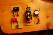
 Let us know.
Here is pic of my boards. Not great but should work Ok. You may notice the transistors are backwards. Forgot to do the negative on the layout in my CAd program. Should still be able to sink everything OK. If you see anything that causes you to shriek, let me know. I'll be firing them up tomorrow. The cap before 317 is 2200 not 22000. My mistake in reading drawing. I have some 18000uF Pana's I will use to replace.
Attachments
- Home
- Amplifiers
- Tubes / Valves
- 6V6 line preamp