I decided to try a very basic unregulated DC heater just for giggles, cause I had some parts laying around. Seems to result in about 10db less noise in the 60/120/180 Hz points vs just AC. More details and some measurements later. But did I do this correctly? I blew the side door off one cap because I had the +/- reversed, but I'm hoping that was the only reason.
Specifically:
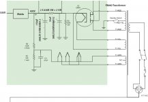
1) is it ok to use the center tap still tied to 80V? Resulted in less noise than when CT attached to 0V in this case.
2) Am I ok with 25V and 16V caps, even with it center tapped to 80V? I think so, since no current flowing there (I think).
I've got about 6.5VDC, but will try trimming it down just a bit more to 6.2 or thereabouts. The 6.3V winding is rated for 5A, so I should be ok even with the power factor loss.
Thanks!
If you can replace that 6,3V transformer with a 12,6 V. Then running thru the full bridge rectifier into the cap there will be enough volts to stuff in a 3-terminal regulator.
")
I've read somewhere that 6.1 will increase the life of the tube significantly.but will try trimming it down just a bit more to 6.2 or thereabouts
I've read somewhere that 6.1 will increase the life of the tube significantly.
I've read that it isn't so much the voltage, but rather controlling the inrush current. A voltage regulator exasperates inrush because it would not allow the voltage to dip at a time when its most benificial for it to dip, at warm up time. But a current regulator will make the tube heat up slowly with no inrush. It doesn't even have to be a chip regulator. Just a dropping resistor fed by a voltage 30 percent or so higher than the tube rated voltage, wasteful yes. But the tube will not inrush.
When metal and the Cathode coating go through wide inrush temperature swings all their life, as opposed to a slower current limited warm up its better. Ever notice how light bulbs always burn out the moment you turn them on? A bulb rarely burns out after its already been on and up to temperature. I liked Salas's filament schematic earlier in this project, where it was set up for current regulation instead of voltage regulation.
Last edited:
There are all kinds of better solutions to what I'm suggesting, especially Salas' original CC solution, but I already have the winding as part of the main transformer and already have the other few parts. Just offering an experiment to see the difference. Will do some listening and also provide some measurements.
More than anything curiosity driving me- and really just learning. This project has def been my most learning project to date. Many kind thanks to everyone here for also making the experience successful and enjoyable as well.
Ok will update the thread next week sometime and happy New years as well!
More than anything curiosity driving me- and really just learning. This project has def been my most learning project to date. Many kind thanks to everyone here for also making the experience successful and enjoyable as well.
Ok will update the thread next week sometime and happy New years as well!
If you can replace that 6,3V transformer with a 12,6 V. Then running thru the full bridge rectifier into the cap there will be enough volts to stuff in a 3-terminal regulator.
If you can replace that 6,3V transformer with a 12,6 V. Then running thru the full bridge rectifier into the cap there will be enough volts to stuff in a 3-terminal regulator.
but I already have the winding as part of the main transformer and already have the other few parts.
What about trying a high current LDO chip to see how it goes with the 6.3VAC only available to you?
Like: MIC29502 - Linear Regulators
I might try that in another iteration if needed. The eBay board below uses that. Easy enough to modify this raw DC version to that if need later I think. For now, I'm enjoying learning the effects of each approach through these simple incremental steps. Less things to blow up at one time too lol
DIY PCB Board - Tube Amp - LV Tube Heater DC Power Supply - 6.3VDC from 6.3VAC | eBay
DIY PCB Board - Tube Amp - LV Tube Heater DC Power Supply - 6.3VDC from 6.3VAC | eBay
Last edited:
Trying some various DC heating, as well as went back to my original AC heating. Regardless, I'm still have some issue with oscillation in one channel, that I have to nail down but cannot as of yet.
It sounds like a pitter patter, low frequency < 10Hz, but also I can hear some overall noise across the spectrum. Unfortunately I didn't take a screen shot, but last time I had it on the analyzer, I can see a -90db peak around 40kHz, then a ringing across the whole audible spectrum from -130 to -100db. Definitely low levels, but I can see and hear something in one channel and not in another.
I have decoupling caps between B+ and gnd at both tubes on the gain stage. I also swapped the 1k Kiwame grid resistors for some 1.2 carbon comps, because I read somewhere that might help. I cleaned up the wiring from RCA input to the resistors, and made sure the leads were as short as possible. I also tried a shielded wire (just one sides shield connected to gnd) on the grid input wire, and also output wire to the coupling capacitor. Nothing seems to have worked just yet.
Because of the non-ideal layout:
one channel (A) is close to the input jack (5cm or so) but far from the output cap (20cm), and the other channel (B) is far from the input (15cm), but close to the output cap (5cm).
The problem is happening on channel (A), which as the longish wire out the output (the wire that connects from below the plate resistor to the capacitor).
Would adding a small resistor, like .47R or something like that possibly help? A little dampening?
Ok, will try to continue to hunt down gremlin. Is the idea of a small R on the output before the output cap a reasonable one? As mentioned, currently there is short wire from RCA to grid, but wire to output is quite long (comparatively), so I was thinking maybe oscillation could occur on the output side rather than grid. Is this unlikely?
Analyzer just confirmed what I was hearing in my hears when connected to amp and speakers, and also not present if I swap wires on the analyzer, so I don't think it's any analyzer anomaly, but always good to double check so I'm hunting actual gremlin vs ghost Cheap RCA cables as well so maybe that has something to do with it. Will try to get some more respectable ones.
Analyzer just confirmed what I was hearing in my hears when connected to amp and speakers, and also not present if I swap wires on the analyzer, so I don't think it's any analyzer anomaly, but always good to double check so I'm hunting actual gremlin vs ghost
Cheap RCA cables as well so maybe that has something to do with it. Will try to get some more respectable ones.Possible clue to oscillation
I am thinking that the oscillation I'm experiencing might be from the power supply. Possible? I did not quite follow the recommended one in post 1.
My preamp was a repurpose from a tubelab SSE, which I had been using with an ST-70 transformer and choke.
I changed out everything from the SSE days, except I left the power supply as it was, and added a maida to clean it up, and drop 100V. I was running the SSE with 6v6's anyway (as a power amp), so figured all was well, and for the most part it is. (was using JJ's with the Tubelab SSE before which can run higher B+, now using Tung-sol reissues)
Anyway, in the attached you will see what I have. I am using a Dynakit PA060 360-0-360, from an ST-70 (new replacement trafo, not an old one). When I use this PSU exactly as drawn here with the 215R after C1, I get the oscillation sometimes. I can't quite qualify when it happens, I think when the amp is running for a few hours.
The tubelab PSU offers the option to replace the 215R resistor with a small choke. That is actually the way I had it when running as a power amp, and always worked like a charm. I have a new C-354 choke, also from an st-70. I just tried to swap in the choke for the 215R. All seems fine in CF mode, but in gain mode I now get the oscillation not just sometimes but always. The C-354 is 1.75H, 62R, 200ma.
So, maybe I'm just overall underdamped? I just tried downloading and running PSUDII to model it, but honestly it's gonna take me a bit of time to figure out how to use it correctly. Without a major overhaul of the PSU, can someone make a few suggestions? Add a resistor here or there? How about adding some R before C1 and the choke I have, as is drawn in post #1?
I also just got a 5U4G recitifier also, so curious to try that out. Maybe that will help too, since it has a little more R internal vs the 5AR4 that I am currently using?
Thoughts?
Attachments
Last edited:
Do you have one or more MOSFET’s in your power supply? They can easily oscillate (a lot).
Regards, Gerrit
I do have a mosfet, in a neurochrome 21st century maida.
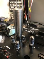
This is a dual build btw- I have a gain stage and CF in one chassis. I can even route one through the other. Attached are some measurements I ran today.
btw, I just added a 215R resistance in series with the L, so I now have a CRLC then maida supply. Not sure that's even kosher, but hasn't improved anything.
I also added a 1R2 carbon comp (all I had around) to the existing 1R0 Kiwame grid stoppers, doesn't seem to have helped.
Seems to be something happening around 32K, not sure what I'm seeing there
Attachments
DING DING DING DING!!!!!
Adamus wins the game. Thank you! Just unplugged the router and everything wifi, and pitter patter, and even the weird ringing you see on the analyzer, gone! See attached.
Still something at 32kHz, but I think that might be the fluorescent lights overhead. Unfortunately I don't have control over them.
But wow, so silly. Thanks again. I wonder what can be done about that in the future. Faraday screen over the tubes?
Anyway, looks like we're all good for now. Thanks again!
Attachments
Last edited:
About oscillation (if it's not just interference)...
So it was interference in the end. Adamus was spot on recognizing it.

Brilliant with the thermos.
- Home
- Amplifiers
- Tubes / Valves
- 6V6 line preamp