
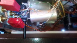
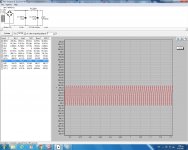
 Successful absolute, Nick no noise at ALL with two extra cables. .... Now I'll put it back again my LDR volume ..
One of these caps is dead (low voltage ) And had the effect of getting output 120dc or more
 stroke my hands....So far so good...
Attachments
Last edited:
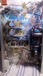
So if I understand well, now you grounded a couple of points you had left floating before? With the yellow cables from heater circuits return sides?
100V caps wouldn't stand the follower circuit's output node DC for long (depending on tube tolerances, usually 125-135V).
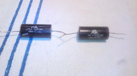
MKP4 Wima 250V is good enough for line level signal, nice that you had some. SCR Tinfoil is usually better saved for loudspeaker crossovers when mounted inside cabinets because it has heavy construction and low microphonics.
100V caps wouldn't stand the follower circuit's output node DC for long (depending on tube tolerances, usually 125-135V).
MKP4 Wima 250V is good enough for line level signal, nice that you had some. SCR Tinfoil is usually better saved for loudspeaker crossovers when mounted inside cabinets because it has heavy construction and low microphonics.
So if I understand well, now you grounded a couple of points you had left floating before? With the yellow cables from heater circuits return sides?
Yes Nick ,with those two yellow cables.
You think the Wima MP4 2.2uf caps are good enough for quality sound or can i go for K75 Russia or other caps..
At the first opportunity I will change all the resistances with Κiwame..
Thanks again for your help and the preamp project (Buffer).
Last edited:
Nice and not much expensive caps look for Milflex caps at the TME shop and for more transparent resistors I prefer Takman metal film.
George!!
Many thanks for your help all this time..
I see... (Milflex caps at the TME shop and for more transparent resistors I prefer Takman metal film.)

I'm super new to tube world, all Solid State before so I encountered a lot of thing that I cant understand why. I hope I can get help from this topic so I can finish my preamp. My problems are:
1. I got 283VAC and 375VDC right after the diode bridge? What ??? I think 283 x sqrt2 ~ 400V - 1.2V diodes = 398V? What am I missing here?
2. One tube heater use 476mA and one tube heater use 489mA to get to about 6.2V. I bought a matched from parts connexion. Are they are bad tubes or this is normal?
Last edited:
1. I got 283VAC and 375VDC right after the diode bridge? What ??? I think 283 x sqrt2 ~ 400V - 1.2V diodes = 398V? What am I missing here?
2. One tube heater use 476mA and one tube heater use 489mA to get to about 6.2V. I bought a matched from parts connexion. Are they are bad tubes or this is normal?
375vdc on diode bridge without any cap or resistor?
Supply the tubes with AC or DC?
I use the lm317 as current limiter and with 0.1Ω resistors i have 6.24 and 6.25 on my tubes.
Last edited:
375vdc on diode bridge without any cap or resistor?
Supply the tubes with AC or DC?
I use the lm317 as current limiter and with 0.1Ω resistors i have 6.24 and 6.25 on my tubes.
It is 375V with 300uf capacitor after diode bridger. The PSU is:
280VAC -> diode bridge -> 300u-220R-270u -> salas 65mA -> 45mA load.
And I measured 375vdc after the diode bridge.
LM317 as current limiter with 0.1R -> 1.25V / 0.1 = 12.5 A ?
I used 2R7 // 100R and 2R7 // 47R for 6.2V heater current.
Your tube seem draw much less current (367mA) than mine. Mine is Tungsol reissued 6V6. Another type of tube?
Voltage drop through 220R show me that only 65mA (actually 64mA) draw. The only thing I can think of is my metter showed me the wrong thing. But I don't have another metter for double check. I used UF5408 didode.
Voltage drop through 220R show me that only 65mA (actually 64mA) draw. The only thing I can think of is my metter showed me the wrong thing. But I don't have another metter for double check. I used UF5408 didode.
Your tube seem draw much less current (367mA) than mine. Mine is Tungsol reissued 6V6. Another type of tube?
Voltage drop through 220R show me that only 65mA (actually 64mA) draw. The only thing I can think of is my metter showed me the wrong thing. But I don't have another metter for double check. I used UF5408 didode.
I think the target for all 6V6 is 450ma.
1.25/450=2.7Ω
15*3.3/18.3=2.7Ω +/- 0.1Ω for trimming or other LM317.
Last edited:
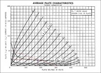
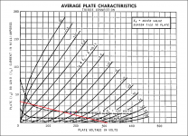
Its closer to a more symmetric portion of the grid lines. But that's an old (maybe GE) datasheet chart and you got 6P6S NOS or Tungsol new production clone tubes so measuring THD with the tubes you use would be the best technical monitoring. Normally there won't be more than 4-5dB THD differences at 1V RMS output level between those points of operation.
Another way is to try listen for difference and if you can't differentiate between those points just keep the most energy efficient one for less CCS setting regarding the regs dissipation.
Another way is to try listen for difference and if you can't differentiate between those points just keep the most energy efficient one for less CCS setting regarding the regs dissipation.
- Home
- Amplifiers
- Tubes / Valves
- 6V6 line preamp