Hello, and a happy new year.
I have been building some parts for this 6V6-preamp of yours, but I have some trouble understanding the workings of the current regulator heater. I have built one heater supply and tried it with two different russian Tung-Sol 6V6's. One of the tubes measures up to exactly 6.3 volts, but the other one gets up to only 5.8 volt. Does that mean that one of the tubes is faulty or do I have to adjust the resistors on one of the supplies to use both tubes?
I have been building some parts for this 6V6-preamp of yours, but I have some trouble understanding the workings of the current regulator heater. I have built one heater supply and tried it with two different russian Tung-Sol 6V6's. One of the tubes measures up to exactly 6.3 volts, but the other one gets up to only 5.8 volt. Does that mean that one of the tubes is faulty or do I have to adjust the resistors on one of the supplies to use both tubes?
Hello, and a happy new year.
I have been building some parts for this 6V6-preamp of yours, but I have some trouble understanding the workings of the current regulator heater. I have built one heater supply and tried it with two different russian Tung-Sol 6V6's. One of the tubes measures up to exactly 6.3 volts, but the other one gets up to only 5.8 volt. Does that mean that one of the tubes is faulty or do I have to adjust the resistors on one of the supplies to use both tubes?
Hello
Tube to tube there are tolerances, the RCA manual says 6V6 heater current should be 0.45A +/- 6%
Measure across the setting resistors for voltage drop and divide it by their confirmed combined value to find the exact running current first because the LM-317 has internal Vref sample to sample tolerance also, as well as the resistors
If its 0.45A exactly then your second tube is -8.6% and maybe not useless but out of spec when it takes to crank its heater current over +6%. It may live shorter as a result
Then again (more likely) the circuit tolerances could have worked against it and you will find lowish heater current that takes adjustment while the other tube is more sensitive than average and heated up to nominal Vh spot on
Happy new year
My 6V6 preamp is up and running. It sounds very nice . The mid range and inner detail is very good. Does it lack just a smidgen of transient attack ? Could be the output coupling cap. Panasonic 22uF 350V elco . Will change to a film type later. There seems to be some loss of sparkle in HF. I'm comparing it to the sound of the power amp direct with the source. The 6V6 seems to loose some amount of 'impact'. The transients seem slightly duller . Maybe the output cap is responsible. I have a few good ones. will try them later.
But there are two major problems.
1. It's extremely microphonic ! Tapping any part of the board is very audible. Tapping the tube is obviously very audible. It's loud ! Both tubes are equally microphonic . Extremely sensitive ! Haven't come across this amount of sensitivity in tubes before. My last triode preamp hardly had any microphony issues( 12AU7 and 6922 ).
2. With ac heaters I get plenty of hum even with the volume at zero. There is a resistor chain across the heater voltage ( 220 + 220 ohms in series). The center is connected to ground. Disconnecting it makes things much worse.
I plan to try it with a dc heater .
But are all 6V6 tubes very microphonic ?
My tube is a Russian version. 6P6S I think ( 6 pi 6 c !)
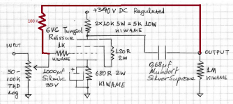
Circuit is like the one at the beginning of the thread
http://www.diyaudio.com/forums/tubes-valves/102352-6v6-line-preamp-9.html
Supply is lower at about 220 V dc . It has a capacitance multiplier using a MJE340 . Rp = 13.5 K ohms . Rk = 680 ohms. Rg = 470 K . No cap in the cathode.
But it does sound very nice. Just need to get the hum out of the way. While playing I don't hear any effect of the microphony !
If I can get back the HF 'bite' ( it doesn't really sound rolled off ) it would be nice as the midrange sounds nicer than the power amp direct to the source ! Must be a addition of the 2nd harmonic content ! Image also seems better for some reason. VERY enjoyable !")
But there are two major problems.
1. It's extremely microphonic ! Tapping any part of the board is very audible. Tapping the tube is obviously very audible. It's loud ! Both tubes are equally microphonic . Extremely sensitive ! Haven't come across this amount of sensitivity in tubes before. My last triode preamp hardly had any microphony issues( 12AU7 and 6922 ).
2. With ac heaters I get plenty of hum even with the volume at zero. There is a resistor chain across the heater voltage ( 220 + 220 ohms in series). The center is connected to ground. Disconnecting it makes things much worse.
I plan to try it with a dc heater .
But are all 6V6 tubes very microphonic ?
My tube is a Russian version. 6P6S I think ( 6 pi 6 c !)
Circuit is like the one at the beginning of the thread
http://www.diyaudio.com/forums/tubes-valves/102352-6v6-line-preamp-9.html
Supply is lower at about 220 V dc . It has a capacitance multiplier using a MJE340 . Rp = 13.5 K ohms . Rk = 680 ohms. Rg = 470 K . No cap in the cathode.
But it does sound very nice. Just need to get the hum out of the way. While playing I don't hear any effect of the microphony !
If I can get back the HF 'bite' ( it doesn't really sound rolled off ) it would be nice as the midrange sounds nicer than the power amp direct to the source ! Must be a addition of the 2nd harmonic content ! Image also seems better for some reason. VERY enjoyable !
Some tips
Its an output stage octal not designed for preamp circuitry so find the best pair you got regarding microphonics and mount them in a shock absorbing manner if you need the 15dB gain version. The buffer version comes out much less microphonic of course. Good in the microphonics department was the new Russian Tungsol. Sylvania VT107 can be good too, black plate RCA also. Some makes and types can be really bad in that, different even as samples.
Get rid of the electrolytic capacitor in the signal path. Use best film cap you can.
Sort out any rail or heater related noise. Use the 317 CCS DC heater circuit, or use that chip normally, one per valve, its clean enough. Scope the rail for noise first, maybe the Gremlin is there.
In the end after those nuisances are solved you are going to have one of the nicest valve preamp sounds. It will always be a valve though, its going to have its valve highlights. Don't expect a strictly monitor sound.
Thanks Salas. I did think of shock mounting the whole board . Currently it sits atop a ( non functional ) sub cabinet just 1 1/2 feet away from the left speaker and I don't hear any microphony effects when playing. Mounting the whole board might be better as it's heavier than the tubes alone.
The hum is coming from the heater section. I will be using a regulated dc supply later today. As it is, it does sound very nice. The electrolytic cap is just a stop gap arrangement. I have some other nice film caps too.
The hum is coming from the heater section. I will be using a regulated dc supply later today. As it is, it does sound very nice. The electrolytic cap is just a stop gap arrangement. I have some other nice film caps too.
When you will fix the issues there is more good sonics to have. The guys here love it for many years. The goal was to get close to biggish DHT triode sound with a poor man's valve. It does the trick in the end but it takes some measures not common when with using novals. Like very good supplies, some selection of 6V6, resilient mounting. In some samples you will even hear the metals expanding while heating up like diiing... (ST bottle can be worse for peculiar sounds). But its a lovely preamp guy if you will be careful. Carries over some of the difficulties of the 30s design preamp builds sans the direct heating and the OPT though. Its not absolute phase correct in the gain version, remember it inverts if it matters to you. You can invert again at the speaker terminals.
Yes you should. This solved the last bit of hum I had.I will be using a regulated dc supply later today.
I did include a 1000uF in the cathode but with a jumper. So I can include it or remove it by using the jumper ! As it stands now, any more gain is not required due to the hum.
I find a lot of other regulators here except the 317's or 7806 or 05 . Will have to take a trip to the market this evening. May as well buy some other parts too !
Since everything is set up to do listening tests, I can't compare it with a regular (noval) triode preamp which I had made earlier.
I find a lot of other regulators here except the 317's or 7806 or 05 . Will have to take a trip to the market this evening. May as well buy some other parts too !
Since everything is set up to do listening tests, I can't compare it with a regular (noval) triode preamp which I had made earlier.
I did include a 1000uF in the cathode but with a jumper. So I can include it or remove it by using the jumper ! As it stands now, any more gain is not required due to the hum.
I find a lot of other regulators here except the 317's or 7806 or 05 . Will have to take a trip to the market this evening. May as well buy some other parts too !
Since everything is set up to do listening tests, I can't compare it with a regular (noval) triode preamp which I had made earlier.
Fix issues first, also find your best operating point or gain mode, then there will be much time to listen more critically. What power amp you use, what is its voltage gain?
OK I rigged up a LM317 in regular voltage control mode. I get 6.5 V which I think is OK. The hum is now almost gone. I can hear slight hum near the speaker but I think that can be fixed overtime. Funnily it is still microphonic but seems less so now !
The sound is still ( ever so slightly ) slightly softer than the direct connection to the power amp. But I suspect the output electrolytic capacitor. I'll put a film in there and check it again. Next couple of days I'm too busy so it will take till the weekend.
But it does sound quite nice on it's own. There is enough gain for me . No need to use the cathode capacitor. But as an experiment I will try it out as I just have to jumper the pins I put there.
I used a 6L6 a few years ago as a similar preamp. I liked the sound very much. I can do that again as I have several 6L6 tubes. Unfortunately I have only these Soviet 6S6P tubes. I will get some Tungsol and Mullard types also to check them out. Wonder if JJ is good enough ? Power amp gain is about x23 = 27.2 dB .
Last edited:
Good progress. Trim it to 6.3Vh or bit less when able, just to save some tube life. The Zo is ~ 1.3K (with cathode resistor cap) so higher than 10K Zin amps help too. The film cap coupler will tighten it up further. What operating point you use right now on the 6V6? B+ Vp Ip?
Although but also because this is a design that finds its beauty in its simpleness I find it no reason not to experiment with it. If not for anything then so for listening and learning. A simple lighter local feedback for example. can do good for Z and for some intermodulation correction if one has the gain to play with.
Also playing around with some elevation of the heaters can do wonders for the microfony. The distance between the heater and the cathode is no more then some layers of oxide so putting some elevation (bias) between them and ease the stress can sometimes change alot.
Also playing around with some elevation of the heaters can do wonders for the microfony. The distance between the heater and the cathode is no more then some layers of oxide so putting some elevation (bias) between them and ease the stress can sometimes change alot.
Attachments
Last edited:
Such a loop-feedback mode experiment would need the 100K to connect at the 1K's grid side leg though. I would use 6.8K feedback resistor so to make it more effective. 100K changes nothing with the open loop gain available. Gain goes down to 8dB is something to consider also (6.8K Rf & Rk bypass included). 20K Rf & 3.3k gridstopper will be an easier impedance resistor network to drive nonetheless.
The drawback of any feedback is of course trying to correct phase deviations. Never does any good and thats the problem with global such. Just sounds bad. Correcting a triodes intermodulation distorsion is what it does best. Short lops. A tranny in between causes problems, and I would expect a slow electrolyth to do the same.
- Home
- Amplifiers
- Tubes / Valves
- 6V6 line preamp